

Abstract
Solid oxide fuel cells (SOFC) are highly efficient energy conversion device, but its high operating temperature (800∼1000 °C) restricts industrial commercialization. Reducing the operating temperature to <800 °C could broaden the selection of materials, improve the reliability of the system, and lower the operating cost. However, traditional perovskite cathode could not both attain the high catalytic activity towards the oxygen reduction reaction and good durability at medium and low temperature range. In contrast to the conventional perovskites, Ruddlesden–Popper perovskites exhibit fast oxygen surface exchange kinetic and excellent stability at medium and low temperatures, and excel both in oxide-conducting fuel cells (O-SOFC) and proton-conducting fuel cells (H-SOFC). In this paper, we try to relate its prominent performance with the crystal structure, main physical properties, and transport mechanism of oxygen ions and protons. We also summarize the current strategy in improving its application in O-SOFC and H-SOFC. Finally, we discuss the challenges and outlook for the future development of RP perovskites in SOFC.
Export citation and abstract BibTeX RIS

Original content from this work may be used under the terms of the Creative Commons Attribution 4.0 license. Any further distribution of this work must maintain attribution to the author(s) and the title of the work, journal citation and DOI.
1. Introduction
Solid oxide fuel cells (SOFC) are highly efficient (up to 80%) and quiet technology that can convert chemical energy directly into electrical energy [1, 2]. It is also favored because diversified fuels can be applied and there will be no carbon dioxide production if hydrogen is used [3–8]. Traditionally, SOFC operates at high temperature range from 800 °C to 1000 °C, which gives rise to the degradation of the material and poor compatibility between the components in the cell. Thus, efforts have been devoted to lowering the temperature to intermediate temperature range, from 650 °C to 800 °C. However, the inferior catalytic activity towards oxygen reduction reaction (ORR) that happens on cathode restricts its application [9, 10]. People have also researched on developing cathodes for proton-conducting ceramic fuel cell (H-SOFC) rather than the conventional oxygen-conducting SOFC (O-SOFC) since H-SOFC can further lower the operating temperature to 450∼700 °C as the lower proton transporting barrier [11]. The optimal cathodes for H-SOFC differs that for O-SOFC in that it is the proton that transporting through the electrolyte to cathode and reacts with the oxygen to produce water, which requires the cathode not only to be high electrical and oxygen-ionic conducting, thermally and chemically compatibility with other components of the cell, it should also be proton-conducting and stable in the humidified atmosphere [12]. Also, unveiling and understanding the proton and oxygen transporting mechanism is helpful for designing efficient cathode and provide instructive information in choosing electrode that could be both used in O-SOFC and H-SOFC.
Perovskites are the most researched cathodes for SOFC so far. Manganese based perovskites, such as La1−x Srx MnO3, show high electrical conductivity and matched thermal expansion coefficient (TEC) with conventional electrolyte, however, it is not applicable in the intermediate temperature range for its low ionic conductivity [13, 14]. Cobalt-based perovskites, such as, Ba0.5Sr0.5Co0.8Fe0.2O3−δ (BSCF) [15] is mixed conductor which can conduct electrons and oxygen ions thus exhibiting promising ORR catalytic activity at lower temperature [15, 16], but it suffers severe degradation by surface segregation of Sr and Co and its big difference in thermal expansion coefficient (>20 × 10−6 K−1) with electrolyte [17, 18]. Also, perovskite-related structures have caught scientists' attention: LnBaCo2O5+δ , such as PrBaCo2O5 and SmBaCo2O5−δ exhibited high ORR catalytic activity [19, 20]. However it encountered severe degradation problems because of its A-site segregation, carbonates formation by CO2 poisoning and mismatch of TEC with the typical electrolyte [21, 22]. Therefore, we are still searching for promising cathodes.
Ruddlesden–Popper (RP) perovskites are considered as potential cathode basing on the fact that RP perovskites do not necessarily contain alkaline-earth metals, which can avoid the surface segregation problems related to its existence that may adversely affect the electrode performance, as widespread in alkaline-earth metal-containing simple perovskites [23]. For example, Druce et al [24] studied RP-structured PrLaNiO4+δ material by using surface-sensitive low energy ion scattering technique and found that there was no segregation of either lanthanide cation in the PrLaNiO4+δ , contrary to the apparent Sr segregation at the La0.6Sr0.4Fe0.8Co0.2O3−δ (LSFC) surface. Another motivation for studying RP-type perovskites is that they possess ORR activity, long-term stability and chemical stability [25, 26]. For example, Bassat et al [27] calculated the ionic conductivity from the oxygen diffusion data, using the Nersnt–Einstein relation, concluding that RP-type Ln2NiO4+δ (Ln = La, Pr, Nd) showed much higher ionic conductivity (σi = (1.5 ∼ 2.3) × 10−2 S cm−1) compared with the simple perovskite LSFC (σi ∼ 3.7 × 10⁻³ S cm−1) and La0.6Sr0.4Fe0.8Ni0.2O3−δ (LSFN) (σi ∼ 1.5 × 10⁻³ S cm−1) at 700 °C. Moreover, RP-structure Ln2NiO4+δ nickelates display intrinsically high oxygen diffusion (D*∼4.15 × 10⁻⁷ cm2 S−1) and surface exchange kinetics (k*∼7.57 × 10⁻⁶cm S−1) relative to the traditional perovskite La0.6Sr0.4Fe0.8Co0.2O3−δ (D*∼5.40 × 10⁻⁹cm2S−1, k*∼9.26 × 10⁻⁸cm S−1) at 700 °C [28]. La1.5Sr0.5Ni1−yFeyO4+δ and La1.2Sr0.8Ni1−yFeyO4+δ reported by Gilev showed fast oxygen surface exchange property [29]. RP series materials provides new options as the cathode for ORR application. In addition, the anode-supported single cells assembled with the Pr2NiO4+δ cathode showed a compatible power density of 650–700 mW cm−2 at 0.8 V cell voltage at 750 °C with LSCF-based cells, however much lower degrading rate of only 1 %–3 % per 1000 h compared to that of LSCF-based cells (10 –20 % per 1000 h) [30]. Laguna–Bercero [31] has evidenced the excellent electrochemical performance and stability of Pr2NiO4-Ce0.9Gd0.1O2−δ (PNO-CGO) cathode for reversible SOFC. Therefore, RP structure is fantastic not only for its high ORR electrocatalytic activity but also the good stability. In the past decades, the composition optimization of RP on physical and chemical properties and its application including SOFC has been conducted. However, a systematic report on the structure, the oxygen and proton transport mechanism and its application in O-SOFC and H-SOFC has not yet been drafted. Therefore, this paper aims to outline the crystal structure, oxygen and proton transport mechanism of RP perovskites, and its application in O-SOFC and H-SOFC.
2. Crystal structure of the RP perovskites
Back in 1958, Ruddlesden and Popper synthesized the RP phase with general formula of An +1Bn O3n+1 [32], and its structure is composed of ABO3 perovskite layer and AO rock salt layer alternately distributed along the c axis [33]. Shown in figure 1 is the structural schematic diagram of An +1Bn O3n+1, A site is usually occupied by a rare earth element or an alkaline earth metal element, and the B site is a transition metal element (Ni, Mn, Cu, Fe) [34].
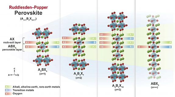
Figure 1. Depicts the ideal tetragonal crystal structure of the Ruddlesden–Popper perovskite An +1Bn X3n+1 (n = 1, 2, and 3) (space group: I4/mmm). The ideal cubic crystal structure (space group: Pmm3) of the simple perovskite ABX3 is also shown, which is equivalent to the case of Ruddlesden–Popper perovskite n = ∞ (adapted from [34] Copyright (2020), Materials Horizons).
Download figure:
Standard image High-resolution imageMany RP perovskites have been modified by doping with different metal ions, and the crystal structure is determined by the radius and valence of the doped metal ions. Doping in the RP perovskites could give rise to the generation of oxygen ion vacancies and the distortion of the angle between the cation and the oxygen, resulting in the structure change. And we will discuss the doping effect on the RP structure by A-site and B-site doping, respectively.
Size effect could be used to illustrate the influence of the low-valence metal ion doping in A-site in RP perovskites on its structure. Doping RP perovskites with lower valence metal in A-site could cause the oxidation of B-site ion to a smaller radius because of the charge compensation [35–40]. For example, Pikalova et al [36] studied Nd2−xCaxNiO4+δ and demonstrated that with the increase of Ca doping, the phase structure changed and the cell volume contracted. The substitution of Nd3+ (r = 1.16 Å) by the larger Ca2+ (r = 1.18 Å) results in the oxidation of the B site ion (Ni2+ (RVI = 0.69 Å) to Ni3+ (RVI = 0.56 LSÅ; 0.60 HSÅ)). Pikalov et al [37] and Sadykov et al [41] also obtained similar phenomenon by researching Nd2−x Cax NiO4+d and Pr2−x Cax NiO4+d. The unit cell has undergone a much more significant deformation along the c-axis with increasing Ca concentration [42]. Grimaud et al [43] reported that the Sr substitution for Pr in Pr2NiO4+δ also resulted in the phase transition of the crystal structure from orthorhombic to tetragonal, as well as changes in lattice parameters and unit cell volume. But the size effect cannot be used to explain the crystal structure change caused by equivalent A-site ion doping. For example, Hu [44] studied the Bi ion-doped cuprate La1.9−x Bix Sr0.1CuO4−δ and found that bismuth doping would cause a small increase in lattice parameters without changing the tetragonal structure (I4/mmm space group), this is because the radius of Bi3+ (RIX =1.24 Å) is similar to La3+ (RIX =1.22 Å). Bi doping will not occupy the A-site since large radius difference of Bi3+ (RVI = 1.03 Å) and Cu2+ (RVI = 0.73 Å) [45, 46]. Garali et al [47] reported that the crystal structure of Eu3+ ion-doped La2NiO4 had a tetragonal structure of the I4/mmm space group, and the lattice contracted slightly because of the doping of smaller Eu3+ for La3+.
B-site doping of RP series oxide will also cause the change in its lattice parameters. Forslund et al [48] synthesized La0.5Sr1.5Ni1−xFexO4±δ and found that the a, c and the unit cell volume increased slightly with Fe doping because of the larger radius replacement of Ni ion (r(Ni3+, LS) = 0.56 Å, r(Ni4+, LS) = 0.48 Å)) with Fe ion (r(Fe3+, HS) = 0.645 Å, r(Fe4+, HS) = 0.585 Å)) [49]. The Cu-doped La2NiO4 material studied by Tarutin et al [35] had a K2NiF4 type crystal structure and a space group of I4/mmm tetragonal crystal, Cu doping caused the crystal structure to expand along the c axis without crystal system change.
The tolerance factor can be used as an important indicator to evaluate the stability of phase structure. It is closely related to the micro-strain in the crystal lattice and can be quantitatively evaluated by the Goldschmidt tolerance factor [50, 51].

where rA, rB, and rO is the ionic radii of the A-site cation, B-site cation and oxygen ion, respectively. It is known that Ln2NiO4+δ structure is stable in the range of 0.866 ⩽ t < 1 [51]. The closer the t value to 1, the higher the stability of the structure. Due to the micro-strain in the crystal structure of A2BO4, the stoichiometric oxygen in the structure arouses a change. For example, Grimaud et al [43] confirmed the high non-stoichiometric oxygen of Pr2NiO4. Figures 2(a) and (b) presents schematic diagram of the twisted structure of Pr2NiO4, the structural stresses will be aroused by the compression of the NiO2 layer when the Pr2O2 layer stretches due to the larger Ni2+ cation. To reduce these stresses, Pr2NiO4 naturally inserts some additional oxygen atoms into the rare earth tetrahedron of the Pr2O2 layer, which makes the Pr–O distance longer and oxidizes Ni2+ (RVI = 0.69 Å) to smaller Ni3+ (RVI = 0.60 Å), depending on the reaction:

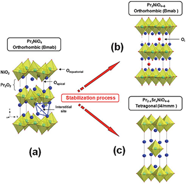
Figure 2. The twisted structure of Pr2NiO4 (a) the stable structure is caused by (b) the oxygen insertion in Pr2NiO4+δ , or (c) the substitution of Pr3+ by Sr2+ in Pr2−xSrxNiO4+δ (adapted from [43] Copyright (2012), Journal of Materials Chemistry).
Download figure:
Standard image High-resolution imageWhen Pr (rPr3+ = 1.179 Å) is replaced by a larger Sr (rSr2+ = 1.31 Å) ion, the value of t increases, and the stability of the phase structure increases. Similarly, Frayret et al [52] confirmed the non-stoichiometric oxygen in La2NiO4+δ by the electronic structure calculation with the density functional theory (DFT). The calculated t value for Ca-doped Nd2NiO4 gradually increases with the Ca doping amount, indicating the stability of the phase structure [36, 38]. Nevertheless, the occupation of cationic positions (Occ. (Nd/Ca)) decreases with increasing Ca doping. The non-stoichiometric oxygen δ of NNO and NCNO calculated from thermogravimetric analysis (TGA) data are 0.25 (2) and 0.11 (1), respectively, indicating a trend of δ decreasing with increasing Ca content [38].
3. Mechanisms of ion transport in RP Perovskites
It is well-known that for SOFC operating at low and intermediate temperature range, ion migration and diffusivity are important factors that determining the effectiveness of the fuel cells [53]. Recently, great efforts have been devoted both in theory and experiment to understand the ion migration mechanism of RP perovskites. In the past few decades, it has been demonstrated that many doped RP perovskites exhibit rapid oxygen surface exchange property, effective overall oxygen migration [29, 54–56]. Due to the different crystal structure of RP-type perovskites from traditional perovskites, its ion transport characteristics and mechanism are different. Since RP perovskites are used as cathodes for O-SOFC and H-SOFC, understanding the transport mechanism of oxygen ions and protons in RP perovskite could provide guiding information for composition optimization. Therefore, we discuss the progress in the transport mechanism of oxygen and proton from theoretical and experimental aspects.
Compared with other perovskites and oxygen ion conductors, RP perovskite oxides contain oxygen vacancies and interstitial oxygen species due to the presence of rock salt layers (AO) in the RP structure. Oxygen transport mechanism of the RP structure changes with different operating condition because of the variation of non-stoichiometry [52, 57–59]. Diffusion in crystalline materials requires the migration of atoms away from their equilibrium positions. Diffusion mechanism describes the way an atom can move from one equilibrium position to the neighboring one [60].
3.1. Oxygen migration properties
There are currently three recognized oxygen ion diffusion mechanisms: the direct interstitial mechanism, interstitialcy mechanism and the vacancy mechanism of diffusion [60]. The direct interstitial mechanism refers to the migration of interstitial ions to the adjacent interstitial site without causing any permanent displacement of the other ions [60]. Frayret et al [52] studied the direct diffusion mechanism of La2NiO4 by studying the electronic structure using density functional theory (DFT), he only considered the interstitial oxygen between adjacent holes in the La2O2.25 layer and concluded that direct diffusion mechanism seems to be determined by the lattice relaxation and oxygen polarizability. Different from the direct interstitial mechanism, interstitialcy mechanism might include the interstitial ions further transfer away from the equilibrium sites [57]. For example, Chroneos et al [61] used molecular dynamic simulation to predict the oxygen diffusion process of La2NiO4, as shown in the figure 3, for predicting interstitialcy mechanism, the oxygen interstitial replaces a top oxygen ion from the NiO6 octahedron, and the oxygen ion transfers to the adjacent oxygen interstitial position. Minervini et al [62] proposed a 'push–pull' mechanism to describe oxygen diffusion through atomic simulation calculations and suggested the generation of Frenkel anion defects (oxygen vacancies and interstitial oxygen) leads to an increase in the extra oxygen content. The oxygen diffusion in perovskites can also be illustrated by the vacancy mechanism of diffusion, oxygen ion diffuses by jumping to a neighboring vacancy [63]. However, vacancy diffusion of the RP-structure is different from perovskite oxide. For example, Parfitt et al [64] studied the oxygen transport in Pr2NiO4+δ through molecular dynamics calculations and found that the oxygen diffusion in Pr2NiO4+δ was highly anisotropic, occurred almost exclusively through the gap mechanism of the a–b plane, while the vacancy transport mechanism along the c axis was limited.
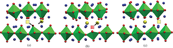
Figure 3. Characteristic snapshots of the interstitialcy diffusion sequence during MD simulations of La2NiO4.09 at T = 900 K. Interstitial oxygen ions and vacancies are represented by yellow spheres and squares respectively (adapted from [61] Copyright (2010), Journal of Materials Chemistry).
Download figure:
Standard image High-resolution imageTo further understanding the mechanism of the oxygen diffusion, the oxygen migration species and migration paths needs to be considered [65]. Oxygen migration jumps by the interstitialcy (push–pull) mechanism, where interstitial oxygen can effectively pass through the peroxide interstitial state [66]. Both neutron scattering experiment [67] and molecular dynamics calculation [61] proved that oxygen ions in Ln2NiO4 (Ln = La, Pr) perovskite are mainly transmitting along the a–b plane through the interstitial process. The oxygen transport of RP materials is mainly accomplished through interstitial and interstitial mediated diffusion mechanisms, while vacancies play a smaller role in diffusion, even for materials with lower stoichiometry [59, 68, 69]. For example, Huan et al [70] further studied the ORR activity of RP materials, and found that it is the concentration of interstitial oxygen ions, the mobility of interstitial oxygen ions and lattice oxygen that governs high ORR activity rather than the oxygen vacancies. Minervini et al [62] had predicted in La2NiO4 that both monovalent and divalent oxygen ions are involved in interstitial migration by atomic calculations. Buttery et al [71] confirmed interstitial oxygen migration in Ln2NiO4 including  species migration. Xu et al [72] found the two oxygen interstitial diffusion mechanisms in La2−xSrxNiO4+δ
materials by DFT. In addition to the proposed interstitial-mediated mechanism, another type of oxide and peroxidation was also discovered. Figure 4 shows the oxide–oxide, oxide–peroxide diffusion mechanism. In the transition state of the oxide–oxide mechanism, the oxide interstitial (Oint2−)atom 'kicks out' the oxygen at the top of the bond with the Ni atom, resulting in the temporary formation of a vacancy. However, the peroxide interstitial (Oint1−) bonds with a top oxygen atom in the rock salt layer to form an
species migration. Xu et al [72] found the two oxygen interstitial diffusion mechanisms in La2−xSrxNiO4+δ
materials by DFT. In addition to the proposed interstitial-mediated mechanism, another type of oxide and peroxidation was also discovered. Figure 4 shows the oxide–oxide, oxide–peroxide diffusion mechanism. In the transition state of the oxide–oxide mechanism, the oxide interstitial (Oint2−)atom 'kicks out' the oxygen at the top of the bond with the Ni atom, resulting in the temporary formation of a vacancy. However, the peroxide interstitial (Oint1−) bonds with a top oxygen atom in the rock salt layer to form an  dumbbell, without generating oxygen vacancies.
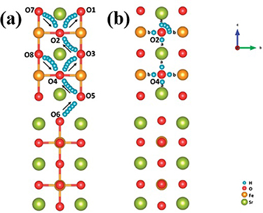
Figure 4. (Left) The diffusion path and energy diagram of the oxide-oxide interstitial-mediated diffusion mechanism. (Right) The diffusion path and energy distribution of the oxide-peroxide diffusion mechanism (Adapted from [72] Copyright (2018), Chemistry of Materials).
Download figure:
Standard image High-resolution imageMoreover, the transport of oxygen has a high degree of anisotropy, where the diffusion of oxygen gaps in the a–b plane is generally higher than that in the c-direction by at least an order of magnitude [74–76]. For example, Xia [73] used DFT method to explore two typical migration paths of oxygen ions in S3Fe2O7−δ and calculated the energy barriers for different oxygen ion migration directions, found that the energy barrier for oxygen ion migration in the [010] direction is lower than that in the [001] direction, confirming that oxygen ion migration occurs mainly in the a–b plane. As demonstrated in figure 5, the maximum migration energy barrier for the oxygen migration along path I is 1.40 eV, which is along the [001] direction: T1→2, T2→3, T3→4 and T4→3, while lower energy barriers of 0.90 eV for oxygen diffusion with path II (T1→2 and T2→5) and path III (T6→7 and T7→8) in [010] direction. Zhang et al [53] comparatively studied the interstitial oxygen transport of RP materials with n = 1 and n = 2, and calculated the relative energy of diffusion on the a–b plane using the CI-NEB (see figure 6), the oxygen migration barrier in n = 2 is about 1.46 eV, which is significantly lower than 1.74 eV in n = 1. For LNO materials, the oxygen ion mobility increases with the number of layers, which is consistent with previous report [77, 78].
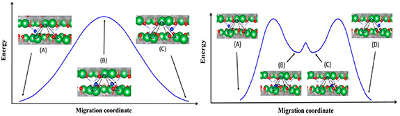
Figure 5. Different oxygen ion migration paths along (a) [001] and (b) [010] respectively (Adapted from [73] Copyright (2016), ACS Applied Materials & Interfaces).
Download figure:
Standard image High-resolution image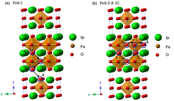
Figure 6. (a)-(b) the interstitial oxygen transmission path of LNO (a) n1 and (b) n2, S1-S3 provide three Oint sites along this path. (c)-(d) LNO (c) n1 and (d) n2 corresponding energy barrier (Adapted from [53] Copyright (2019), Journal of Materials Chemistry A).
Download figure:
Standard image High-resolution image3.2. Proton diffusivity properties
The migration of protons in perovskite or perovskite-like materials follows the two-step Grotthuss mechanism which is accepted by most people [66, 79–82]. The main characteristics of proton defect transmission includes rotational diffusion and octahedral jumping (protons jump from one oxygen ion to another adjacent oxygen ion in the same octahedron), that is, protons only show long-distance diffusion, while oxygen remains in its crystal position [79]. For example, Hermet et al [80] revealed the proton transport of BaCeO3 perovskite that there are two processes of proton transport: reorientation and transfer (or hopping), protons may jump directly from one octahedron to another (jumping between the octahedrons rather than the intraoctahedral hoppings). By using theoretical (first-principle) and experimental methods, Wang et al [81] investigated two possible proton migration processes, and found that highest proton migration barrier was about 0.63 eV, which is in agreement with the experimental findings. It should be pointed out that the exact mechanism of proton transport in RP-type perovskite has not been determined by research activities [82]. Researchers generally use the proton transport mechanism in perovskite materials to explain the proton transport in RP-type materials. Proton diffuse to RP-structure Sr3Fe2O7−δ (SFO) surface via the combination of two typical paths: the proton intra octahedral hopping and the proton reorientation around O ions, as illustrated in figures 7(a) and (b), respectively [65]. The transfer of protons across the rock-salt layer (O6 to O5) is the most difficult process with the highest energy barrier of 0.67 eV.
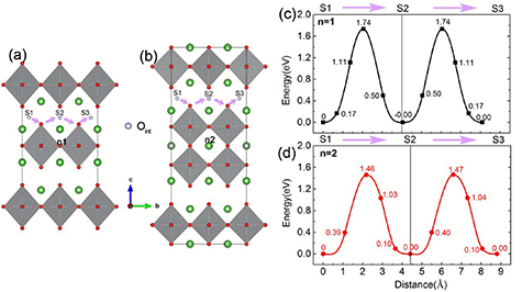
Figure 7. Schematic diagram of the proton transporting, (a) proton intraoctahedral hopping pathways and (b) the proton reorientation around O (Adapted from [65] Copyright (2018), RSC Advances).
Download figure:
Standard image High-resolution imageThe possible location of proton defect formation in RP perovskite oxide was demonstrated by DFT [83]. As shown in figure 8, Sr3Fe2O7−δ proton defects may form on three different oxygen atoms, d1, d2 and d3, respectively, and the lowest proton formation energy at d3 indicates that proton defects are more likely to be formed at d3 [83]. Proton transfer is achieved by the two-step Grotthuss diffusion mechanism [84, 85], which involves the rotation of the proton around an oxygen site (R) and proton transfer between adjacent oxygen ions (T) [86]. For example, Wang et al [83] studied SFO cathode and found that the proton migrates along the direction of [001] and [010] by means of rotation (R) and transfer (T) as shown in figures 9(a) and (b). It reveals that proton diffusion in perovskites along the direction [010] has a greater advantage than through the SrO layer [001]. An overall proton migration pathway along the [001] and [010] direction can be summarized as the following process: T12/R23/R34/T45/T56 and T12/T23/R34/R45. The [001] direction offer the highest migration barrier of 0.62 eV higher than the migration of [010] direction (0.28 eV). It is generally accepted that a smaller energy barrier along the path favors proton diffusion. Chen et al [87] performed by comprehensive calculation that the proton migration in Sr3Fe2O7−δ is more likely to occur in the [010] layer. In addition, Zhang et al [53] disclosed the proton transfer of RP series LNO (n = 1 and 2) materials, and it turned out that the highest migration barrier (1.66 eV) in n = 1 was greater than that in n = 2 (1.29 eV), which led to the faster proton diffusivity of LNO materials with n = 2, which is caused by the difference of the effective charge of proton, in which the average value of proton n = 2 (0.522e) is higher than that in n = 1 (0.459e).
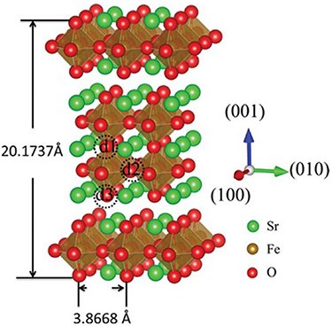
Figure 8. The crystal structure of Sr3Fe2O7−δ oxide. d1–d3 represent three types of oxygen sites that may form proton defects (adapted from [83] Copyright (2015), Journal of Materials Chemistry A).
Download figure:
Standard image High-resolution image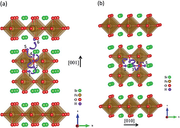
Figure 9. The schematic diagram of proton transmission along (a) [001] and (b) [010] directions (adapted from [83] Copyright (2015), Journal of Materials Chemistry A).
Download figure:
Standard image High-resolution imageFrom the experimental perspective of exploring the diffusion mechanism, electrical conductivity relaxation (ECR) methods are often used to determine chemical oxygen bulk diffusion coefficient (DChem) and chemical surface exchange coefficient (kChem). For example, Hu et al [44] studied the oxygen transport performance of La1.9−xBixSr0.1CuO4−δ using ECR technology, it was shown that LBSC2 (x = 0.2) has much higher kChem and DChem compared with LBSC1 (x = 0.1). At 800 °C, kChem for LBSC2 is 7.7 × 10⁻⁴ cm s−1, about 15% higher than that of LBSC1, whereas DChem is 1.5 × 10⁻⁵ cm2 s−1, twice as that for LBSC1. He ascribed the enhanced oxygen transport performance to the extra oxygen vacancies formation and higher active oxygen concentrations by Bi doping. Furthermore, the faster apparent values of DChem and kChem achieved with increased time of annealing was studied by Saher et al [88], it was found that the two parameters increased with the increase of the annealing time and tended to be stable after 80 h. The apparent values of DChem and kChem were about one order of magnitude higher than the initial value. 18O/16O isotope exchange using secondary ion mass spectrometry and temperature programmed isotope exchange (TPIE) are the latest methods for measuring DChem and kChem [89]. Gu et al [90] adopted the isotope oxygen exchange model to explore the effectiveness of the oxygen exchange process of La2NiO4, they confirmed O2 decomposition as rate-determining step. Sadykov et al confirmed that oxygen diffusion is the rate-determining step the in Pr2−xCaxNiO4+δ material by the TPIE data model [41]. Chen et al [76] pointed out that the oxygen diffusion coefficient of (La0.5Sr0.5)2CoO4 with different crystal orientations: LSC50 (100) and LSC50 (001) were 1.20 × 10⁻¹³ cm2 s−1 and 2.97 × 10⁻¹⁴ cm2 s−1 respectively, and the oxygen diffusion coefficient along the a–b plane in LSC50 was at least 4 times faster than that along the C axis.
4. Essential property of cathode
4.1. Mix ionic-electronic conduction
The ionic/electron conduction in RP perovskite materials occurs due to the redox reaction or the change in the valence state of the transition metal at the B site caused by the difference in the valence state of the host and dopant [91]. Figure 10 summarizes the electrical conductivity of some RP structure materials when n = 1 and n>1. On the whole, the conductivity for RP materials when n = 1 varies widely, ranging from a few to hundreds of S cm−1. Comparing the electrical conductivity of LNO series, the electrical conductivity increases as the number of n increases (La4Ni3O10−δ > La3Ni2O7−δ > La2NiO4+δ ) [78]. This is related to the higher oxygen migration barrier of the RP with n = 1 than that of the n = 2 material, as reported by Zhang et al [53]. When measuring conductivity, the conductivity increases with increasing temperature at low temperatures, but the conductivity decreases at higher temperatures [25, 73, 92]. The former is due to thermally activated semiconductor properties, while the latter is related to oxygen release from oxides [93]. The loss of lattice oxygen at high temperatures leads to decrease in charge carrier concentration or the annihilation of electron holes, as shown in equation (3) [94]:

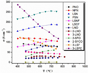
Figure 10. The conductivity of RP materials in the range of 350~850 °C. (Pr2NiO4+δ (PNO) [39], Nd1.5Pr0.5NiO4+δ (NPN) [95], La1.2Sr0.8NiO4 (LSN) [96], Pr1.2Sr0.8NiO4 (PSN) [96], La1.2Sr0.8Ni0.6Fe0.4O4+δ (LSNF) [97], La0.6Sr1.4Co0.2Fe0.8O4+δ (LSCF) [98], La2NiO4 (LNO) [78], La3Ni2O7 (2-LNO) [78], La4Ni3O10 (3-LNO) [78], Sr3Fe2O7−δ (2-SFO) [73], Sr3Fe1.8Co0.2O7−δ (2-SFCO) [73], LaSr3Fe3O10 (3-LSF) [99], LaSr3Fe1.5Co1.5O10 (3-LSFC) [99]).
Download figure:
Standard image High-resolution imageManthiram found similar trends in temperature dependence of conductivity in Sr2.7−xCaxLn0.3Fe2−yCoyO7−δ and Sr3.2−xCaxLn0.8Fe1.5Co1.5O10−δ [92, 100]. Shown in figure 11 is the relationship between the conductivity and the temperature [73]. The decrease in conductivity at high temperature is due to the formation of oxide ion vacancies, causing the reduction of Fe4+ to Fe3+ or Co4+ to Co3+, resulting in a diminution of the carrier concentration [101]. However, the electronic conductivity of undoped RP perovskite oxides at intermediate temperature is not sufficient for its application as cathodes for SOFC. Therefore, people are using doping strategy to increase its performance. A-site doping is generally used to replace the rare earth elements with alkaline earth metals (Sr, Ba, Ca), aiming at improving the electronic conductivity of the material. The results showed that there is an optimal ratio of A-site doping that can enhance the electrical conductivity. For example, Pikalova et al [36] found that the conductivity of Ca doped Nd2NiO4+δ materials increased firstly and then decreased with the Ca2+ doping amount.
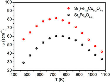
Figure 11. Electrical conductivities of SFO and SFCO measured at various temperatures (adapted from [73] Copyright (2016), ACS Applied Materials & Interfaces).
Download figure:
Standard image High-resolution imageReplacing small amount of Nd3+ with Ca2+ leads to the increase of electron hole concentration and the p-type electron conductivity due to charge compensation (see equation (4)) [38, 39]. However, the excessive Ca2+doping would lead to decreasing the conductivity. The conductivity deterioration can be associated with the possible formation of electrically neutral defect associates [102, 103] or the formation of NiO impurity phase. The same phenomenon is also observed as to Pr2−xCaxNiO4+δ [39, 41].

Yang et al [104] found that the electrical conductivity of Pr2−xSrxNiO4 at 800 °C increased from 70.64 to 121.51 S cm−1 with increasing Sr doping. Manthiram et al [100] studied the effect of the A-site ion radius of Sr3.2−xCaxLn0.8Fe1.5Co1.5O10−δ on the conductivity and found the electrical conductivity decreased with decreasing A-site doping radius mainly because of the decrease of the overlapping of O2p orbital and the Co/Fe3d orbital [105]. Hu et al [44] reported that the conductivity of La1.9−xBixSr0.1CuO4−δ decreased with the bismuth doping as charge carriers would be consumed to form extra additional oxygen vacancies in equation (5), as evidenced by the increased non-stoichiometric ratio of oxygen δ via iodometric titration and thermalgravimetric analysis.

In addition to the alkaline earth metal doping, the B-site transition element, such as Cu and Co doping also has a certain effect on the electrical conductivity. Zhang et al confirmed Cu-doped Nd1.5Pr0.5NiO4+δ material with significantly improved conductivity of 140 S cm−1 [95] and it was explained that the replacement of the Ni2+ (0.69 Å) with larger Cu2+ (0.73 Å) facilitated the hole jumping to the next adjacent B cation because of the decreased distance of the adjacent BO6 units [106]. Zhao et al [107] also found electrical conductivity improvement of Cu doping in La1.5Pr0.5NiO4. However, the conductivity of Cu-doped La2NiO4+δ decreased, which was considered by Tarutin et al to be ascribed to the decreased charge carrier concentration in Cu-doped compounds [35]. The influence of doping on the conductivity is complex and diverse, it is determined not only by the doping ions, amount of doping and the doping location, it is also affected by the preparation condition and the temperature dependence.
4.2. Thermal expansion behavior
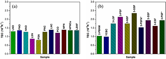
The thermal expansion coefficient (TEC) becomes an indispensable parameter when considering a promising cathode for SOFC as the lifetime of cell will be seriously attenuated if a mismatch of the thermal expansion behavior within the cell occurs [108]. The coefficient of thermal expansion refers to the change of the thermal behavior of the material, in other words, different physical behaviors on temperature [91]. The thermal expansion of perovskite and perovskite-related materials is attributed to physical expansion and chemical expansion [89]. The physical expansion is the crystal expansion caused by the harmonic atomic vibration that comes from the electrostatic attraction in the lattice [109]. The chemical expansion is caused by the partial reduction of B-site cations or the spin transition of B-site cobalt ions [100]. Figure 12 displays the TEC of some layered perovskite materials, mainly RP materials. Broadly speaking, the RP with multi AO rock layers exhibits larger TEC compared to that with one AO rock layer, and the TEC values of La1.2Sr0.8NiO4 and Pr1.2Sr0.8NiO4 are the lowest, which are 8.7 × 10⁻⁶ and 8.0 × 10⁻⁶K−1, respectively [96]. Sr3.2La0.8Fe1.5Co1.5O10−δ exhibited different TEC of 9.24 × 10⁻⁶ K−1 and 17.11 × 10⁻⁶ K−1 in 30 °C–300 °C and 300 °C–900 °C, respectively, because of the formation of oxygen vacancies due to the reduction of cobalt and iron to larger ions [100]. This is also consistent with the findings at Sr2.7−xCaxLn0.3Fe2−yCoyO7−δ materials reported by Manthiram et al [92]. The Co-containing RP perovskites usually have a higher TEC, mostly because of the transition of Co3+ cation from low spin (LS, 0.545 Å, t6 2ge0 g) to high spin (HS, 0.61 Å, t4 2ge2 g) [110]. The larger high spin Co3+ brings about an increase in TEC corresponding to lattice expansion [111]. The TEC value of the cathode must be between 10 ∼ 13 × 10−6K−1 in order to be compatible with other SOFC components [112]. Researchers generally use dopants to decrease the TEC of cathode materials. For example, Manthiram et al confirmed that Ca substituted LaSr3Fe3O10−δ and Sr3.2Ln0.8Fe1.5Co1.5O10−δ can shorten the bond length between cations and oxygen anions, resulting in cell volume shrinkage and decrease in TEC [92, 100]. It was found by Hu et al that Bi doped LaSr0.1CuO4−δ (LSC) has reduced the TEC from 13.3 × 10⁻⁶ K−1 to 9.2 × 10⁻⁶ K−1 [44]. It is significantly lower than the TEC of typical electrolytes, such as 12.2 × 10⁻⁶ K−1 for Ce0.8Sm0.2O2-δ (SDC) and 10.5 × 10⁻⁶ K−1 for yttria stabilized zirconia (YSZ) [112, 113].
Figure 12. The TEC of layered perrovskite, mainly R-P perrovskite materials (a) single-layer materials and (b) multilayer materials. (La2NiO4+δ (LNO) [28], Pr2NiO4+δ (PNO) [28], Nd2NiO4+δ (NNO) [28], La1.2Sr0.8NiO4 (LSN) [96], Pr1.2Sr0.8NiO4 (PSN) [96], La2Ni0.5Cu0.5O4+δ (LNC) [114] , Pr2Ni0.5Cu0.5O4+δ (PNC) [114], Pr2CuO4 (PCO) [115] , Nd1.5Pr0.5NiO4+δ (NPN) [95], Nd1.5Pr0.5Ni0.9Cu0.1O4+δ (NPNCu) [95], La1.2Sr0.8Ni0.6Fe0.4O4+δ (LSNF) [97], Pr2BaNiMnO7−δ (2-PBNM) [116], Y0.8Ca0.2BaCo4O7+δ (YCBC) [117], LaSr3Fe3O10−δ (3-LSF) [26], PrSr3Fe3O10−δ (3-PSF) [26], NdSr3Fe3O10−δ (3-NSF) [26], GdSr3Fe3O10−δ (3-GSF) [26], PrSr3Fe2.9Ni0.1O10−δ (3-PSFN*) [118], SmSr3Fe3O10−δ (3-SSF) [26], EuSr3Fe3O10−δ (3-ESF) [26], and PrSr3Fe3O10−δ (3-PSF*) [118]).
Download figure:
Standard image High-resolution image
Besides A-site doping, doping on B-site can also influence the TEC of the material. Zhang et al [95] found that TEC for Cu-doped Nd1.5Pr0.5NiO4+δ has reduced to 13.6 × 10⁻⁶ K−1. Tarutin et al [35] also concluded the decrease in TEC gradually with increasing Cu doping in La2NiO4. Zhao et al [107] confirmed that introducing a small amount of Cu at the Ni site can effectively reduce the value of TEC. The doping of B-site transition metals in RP perovskites does not always bring a positive effect. Replacing Co with Mn and Fe in RP perovskites could lower the TEC value, in the meantime, it will also cause the decreased electronic and ionic conductivity. Therefore, in the development of SOFC cathode materials, it is necessary to find a suitable compromise between the high conductivity and the matched thermal performance with other cell components [108].
5. Application of RP perovskites as cathode for SOFC
RP perovskite oxide is promising cathode for intermediate temperature SOFCs (IT-SOFC) due to its unique structure, rapid oxygen surface exchange kinetics, and excellent stability in atmosphere. Many researchers are committed to exploring optimal composition and structure to achieve high electrochemical performance of RP perovskites cathode. The reaction of O-SOFC and H-SOFC at the cathode is different, so as to the transport mechanism. Therefore, we discuss the application of RP perovskites as cathode in O-SOFC and H-SOFC respectively.
5.1. RP perovskites as cathode for O-SOFC
The operating temperature for oxygen-conducting type IT-SOFC is in the range of 650~800 °C. Composition optimization of the single phase and composite cathodes fabrication are the most common schemes to applying RP perovskites as cathode for SOFC in different scenarios. A-site and B-site doping in perovskites has considered to be effective method to modify the ORR catalytic activity [119]. Recently, most scholars have adjusted the relationship between structure and performance by changing the composition of RP oxides to improve cathode performance. Generally, substitution at the A position in RP perovskites refers to partial replacement of rare earth elements with alkaline earth metals (Sr, Ba, Ca) [39, 120–122]. For example, Yang et al [104] prepared Pr2−xSrxNiO4 by a glycine-nitrate process, it was found that the area specific resistance (ASR) of the Pr2−xSrxNiO4 is the minimum when x = 0.4. In addition, Sharma et al [123] found that the Rp of Pr-doped La2−xPrxNiO4+δ cathode became smaller with the increase of x at 600 °C, while the thermal stability decreased. This requires compromise between stability and electrochemical performance. When x = 1, LaPrNiO4+δ phase had excellent long-term stability in a symmetrical state (operating at 700 °C for 500 h). In addition, a number of studies have shown that reasonable substitution of transition elements such as Co, Fe and Cu can effectively improve the performance of the cathode [83, 107, 124–126]. The ORR catalytic activity of cobalt-based RP is the highest, but there are some problems such as high coefficient of thermal expansion and poor stability. Therefore, Fe was used instead of cobalt to obtain suitable TEC and stability. Boulahya et al [25] reduced the TEC of the Eu2SrCo1.5Fe0.5O7 cathode by partially replacing Co with Fe. The area specific resistance at 700 °C in air was 0.26 Ω cm2. The composites of Eu2SrCo1.5Fe0.5O7 and Gd0.1Ce0.9O2-δ (CGO) were heated at 900 °C (70:30 wt%) for 12 h without any reaction or decomposition, indicating that these cathode compounds had good long-term stability. The La2Ni1−xCuxO4+δ material showed highest conductivity at Cu substitution amount of 0.4, and the lowest ASR value could be obtained by using La0.9Sr0.1Ga0.8Mg0.2O3-δ (LSGM) electrolyte for its matched TEC with LSGM [120, 127]. Some researchers also improved the electrocatalytic performance and stability of fuel cells by co-doping [40, 98, 128, 129]. Navarrete et al [129] studied co-doping of LNO with Pr and Co and found that La1.5Pr0.5Ni0.8Co0.2O4+δ cathode exhibited the lowest electrode polarization resistance and activation energy values in the temperature range of 450~900 °C and a maximum power density of ∼400 mW cm−2 at 700 °C using pure hydrogen and air.
Although doping has been conducted to optimizing the ORR catalytic activity, however, it is still hard to compromise with sufficient electrical conductivity and suitable TEC. By designing composite cathode via mechanical mixing and infiltration provides novel insight in further improving the electrochemical performances and stability. RP perovskites have good oxygen surface exchange property but low electrical conductivity and large TEC, by mixing with the electrolyte, the TEC and the oxygen ionic conductivity will be modified, thus effectively improving the thermal compatibility between cathode and electrolyte and enhancing the stability and durability of cell performance. The La2NiO4–SDC composite electrode was successfully fabricated by an infiltration method that was studied to be a stable cathode as no obvious degradation was observed after running at 650 °C for 210 h [130], the maximum power density at 800 °C with hydrogen as fuel gas was 550 mW cm−2, which was higher than similar cell by using Pt-YSZ cathode [131]. Sharma et al [132] detected a great decrease of Rp by adding 50 wt% CGO electrolyte into La3Ni2O7−δ (L3N2) from 1.00 Ω cm2 to 0.03 Ω cm2 at 700 °C, and no chemical reactivity between L3N2 and CGO was observed when being heated in air at 900 °C for 2 weeks. Shirani et al [133] systematically studied the performance of (Nd0.9La0.1)1.6Sr0.4Ni0.75Cu0.25O3−δ (NLSNC4) and Ce0.8Sm0.2O2-δ(SDC) composite cathode materials and found that the Rp of the composite cathode decreased firstly and then increased with the SDC content at 800 °C, and NLSNC4 with 50 wt% SDC showed the minimum ASR of 0.12 Ω cm2, however, its conductivity decreased with the increase of SDC content. Chiu et al [115] studied the effect of a series of weight percentages of SDC on the electrochemical performance of Pr2CuO4 (PCO)-SDC composite cathode, Pr2CuO4 (PCO)-10 wt% SDC composite cathode showed the lowest area specific resistance of 0.35 Ω cm2 and the maximum power density of 347.50 mW cm−2. Chen [134] reported a new type of Nd2NiO4−δ (NNO) composite cathode impregnated with scandia stabilized zirconia (SSZ) showed excellent power density of 1.26 W cm−2 and the ASR of the cathode was 0.04 Ω cm2 at 800 °C. RP perovskites cathode has high oxygen surface exchange coefficient and stability, so it is one of the choices as protective layer for SOFC cathode. Some people have studied the composite of RP perovskites and perovskites by solution infiltration method. Li et al [135] observed 40 % polarization resistance drop of infiltrated La2NiO4@La0.6Sr0.4Co0.2Fe0.8O3 (LSCF) to 0.31 Ω cm2 from 0.54 Ω cm2 at 750 °C. The La2NiO4@PrBa0.5Sr0.5Co1.5Fe0.5O5+δ (LNO@PBSCF) cathode with LNO protective layer also exhibited good tolerance to Cr poisoning, the LNO coating effectively prevented the reaction between the volatile Cr species and the PBSCF cathode when treated at 750 °C for 1200 min [136].
5.2. Application of RP perovskites as cathode for H-SOFC
RP perovskites exhibit encouraging performance as cathode in O-SOFC. Recently, researchers are also working on the application of RP perovskites as cathode in proton-conducting SOFC, which is a potential alternative to traditional oxide ion-conducting SOFC [89]. Compared with traditional SOFC, H-SOFC has lower working temperature (450~700 °C) and usually composed of a proton conductive electrolyte, through which the protons transport from the anode to the cathode and produce water. Therefore, the cathode for H-SOFC is even more demanding. Proton migration is accomplished through Grotthuss mechanism in SOFC [66], which mainly occurs in the a–b plane. The electrolyte for H-SOFC is different from O-SOFC. Iwahara [137, 138] firstly reported promising proton conductors such as SrCeO3 and BaCeO3. Currently, the commonly used proton conductors are barium ceratebased materials, such as BaZr1−xYxO3−δ (BZY) and BaCe1−xZrxYyO3−δ (BCZY) [89]. In H-SOFC, it will be beneficial if the cathode has both proton and oxide ion conductivity, because it can expand the reaction area in the cathode. In order to realize this idea, recent research work has focused on applying traditional O-SOFC cathodes into H-SOFC to test its electrochemical performance and stability under humidified atmosphere. For example, Yang et al [96] reported that Ln1.2Sr0.8NiO4 (BZCY) (Ln = La, Pr) can maintain a stable structure within 100 h in humid air (20% vol H2O) at 800 °C. Peng et al [125] studied the Rp of Co-doped La3Ni1.9Co0.1O7 cathode changed from 1.12 Ω cm2 to 0.35 Ω cm2 at 650 °C, and its maximum power density at 700 °C was 0.398 Wcm−2. Zhang [53] reported that Co or Cu doped La2NiO4/La3Ni2O7 accelerated the proton diffusion of the material due to its low migration energy along the path. Wang et al [116] proved that Mn-doped Pr2BaNi2O7−δ at the B site has enhanced oxygen diffusion and proton diffusion property. The single cell composed of BZCYYb-based electrolyte had a peak power density of 1070 mW cm−2 at 700 °C and had no degradation at 0.7 V at 600 °C for 100 h. Miao et al [97] successfully synthesized Sr and Fe co-doped La2NiO4 cathode, the cell based on La1.2Sr0.8Ni0.6Fe0.4O4+δ cathode exhibited high maximum power density (MPD) of 781 mW cm−2 and low polarization resistance 0.078 Ω cm2 at 700 °C, which also showed excellent stability after operating at 600 °C for 100 h. Therefore, co-doping Sr and Fe could be considered as promising strategy in improve electrochemical performance without increasing TEC.
Recently, the composite cathode composed of RP perovskites with proton-conducting electrolyte has shown encouraging performance in H-SOFC. For example, Wang et al [83] found that the MPD of Sr3Fe2O7−δ -5 wt% BaZr0.3Ce0.5Y0.2O3−δ composite cathode at 600 °C is 530 mW cm−2, which is better than PrBaCo2O5+δ -BZCYZ (266 mW cm−2) [139] and Sm0.5Sr0.5CoO3-δ-BaZr0.3Ce0.5Y0.16Zn0.04O3−δ (BZCYZ) (364 mW cm−2) [140]. More importantly, no discharge decay was observed during the 100 h test. Li et al [141] confirmed that 43.6 wt.% (Pr0.9La0.1)2(Ni0.74Cu0.21Nb0.05)O4−δ (PLNCN) impregnated BaZr0.1Ce0.7Y0.2O3−δ (BZCY) electrode achieved the maximum power density of 0.77 W cm−2 at 700 °C, which is significantly higher than other cathodes such as LSCF-BZCY [142], and it did not show any degradation at 600 °C for 200 h. Fu et al [143] added BZCY to the (LaSr)0.9Fe0.9Cu0.1O4 (LSFCu) cathode to increase the ion conductivity and minimize the thermal mismatch between the electrode and the electrolyte. The area specific resistance at 800 °C is 0.19 Ω cm2, and the peak power density is 573 mW cm−2 at 800 °C in humidified H2.
6. Conclusion and perspective
The crystal structure, oxygen ion and proton transport mechanism and main properties of RP perovskites are introduced in this article. RP perovskites have also demonstrated excellent performance in O-SOFC and H-SOFC, which is generally believed to be related to their fast surface oxygen exchange property and its characteristics of oxygen transport and proton transport mechanism. The oxygen transport property of RP perovskites mainly depends on the interstitial oxygen transport, and the oxygen and proton diffusion on the A-B plane of RP structure at a faster rate than along the C axis. Furthermore, the crystal structure, conductivity, TEC and ion transport can be specially regulated by doping the chemical element composition of simple RP perovskites. Appropriate doping ratio can produce more non-stoichiometric oxygen vacancy and realize defect design, which has great influence on the oxygen ion transport properties. At the same time, the comprehensive regulation of its crystal structure, diffusion mechanism, conductivity and TEC will be conducive to its more effective application in SOFC.
In addition, long-term stability is one of the most important considerations in practical SOFC applications. On one hand, RP perovskites applied in O-SOFC as relatively more stable cathode, it could be used as protective layer for its superiority in Cr tolerance and fast oxygen surface exchange property. On the other hand, H-SOFC is expected to be a promising solution for long term operation for it usually operates at lower operating temperature range in 450~700 °C. However, the cathode for H-SOFC has more stringent requirements on the cathode, such as sufficient proton conductivity, stability in humidified atmosphere and even good tolerance to Cr and CO2 poisoning from the interconnect and the air. Although RP-perovskites is relatively more stable and Cr-tolerant in O-SOFC, Cr poisoning on the electrode in H-SOFC will be intensified due to the production of water at the cathode. Therefore, the development of cathodes that are self-stable and Cr-tolerant with metal interconnects under wet air conditions is of great importance as we advance their commercialization and large-scale power generation. At the same time, with the advent of the era of hydrogen energy, we should also actively explore the application of RP perovskites as electrode for solid oxide electrolysis cells, and further promote efficient hydrogen production technology with clean and renewable energy.
Finally, the kinetics of ORR mechanism of cathode for SOFC remains to be studied. An in-depth understanding of the effects of oxygen surface exchange, charge transfer, bulk and surface ion diffusion, and electrical conductivity on electrochemical performance will commute to understand how to improve electrocatalytic performance in principle. The ORR of RP perovskites as cathode for H-SOFC is even more complex and not very clear yet for the participation of proton. Therefore, further exploration on the effect of the defect chemistry and transport property on the ORR kinetics of the RP oxide cathode in H-SOFC should be made, so as to provide instructive information for efficient applications.
Acknowledgments
The project was financially supported by the National Natural Science Foundation of China (51702090, 62004064) and National Key Research & Development Project-International Cooperation Program (2019YFE0107100).