Abstract
The Full-disk MagnetoGraph (FMG), a payload onboard the Advanced Space Solar Observatory (ASO-S), will measure the vector magnetic field in the photosphere. The instrument consists of a front-window filter, a telescope, an LCVR polarimeter, an image-stabilization system, a seven-stage tunable Lyot filter, a CMOS camera with 4096×4096 pixels and a pair of calibration/focus wheels. In this paper, we describe the design of the FMG instrument and provide a summary of test observations carried out with the FMG prototype.
Export citation and abstract BibTeX RIS
1. Introduction
The aim of the Advanced Space Solar Observatory (ASO-S) mission is to improve understanding of the physical processes involved in solar flares, coronal mass ejections (CMEs) and the solar magnetic field evolution (Gan et al. 2019). Thus, the magnetic field is the preferred physical parameter measured by ASO-S. The Full-disk MagnetoGraph (FMG) will measure the photospheric magnetic fields of the entire solar disk with high spatial and temporal resolution, and high magnetic sensitivity. The main performance and parameters are outlined in Table 1.
Table 1. Main Performance and Parameters of the FMG
| Parameters | Value |
|---|---|
| Working Spectral Line | Fe i 532.4 nm |
| Field of View | 34' |
| Aperture | 14 cm |
| CMOS Detector | 4k×4k 12.8 μm |
| System-wide Spatial Resolution | 1.5'' (Pixel Resolution:0.5'' pixel−1) |
| Effective Focus Length | 5355.76 mm (F number: F/38.26) |
| Temporal Resolution | Normal mode: 30 s (single component); 2 min (vector magnetogram) |
| Burst mode: 8 s (single component); 30 s (vector magnetogram) | |
| Data rate | 96 MB min−1 (max.), 140 GB d−1 |
| Longitudinal Sensitivity | 15 G (normal mode) |
| Birefringent Lyot Filter | FWHM: 0.1 Å |
| Working temperature: 22 ± 2°C | |
| Wavelength stabilization: < 0.02 Å | |
| Image-stabilization Accuracy | 0.25'' |
| Dimensions | Optics package: 1335 mm × 790 mm × 380 mm |
| Electronics box: 340 mm × 260 mm × 260 mm | |
| Weight | 101 kg |
| Power | 265 W |
The FMG instrument consists of four parts: an optics package, an electronics box, a harness to connect the first two to the satellite and a thermal control system. This paper is arranged as follows. The FMG Optics Package (FOP) layout is described in Section 2. We introduce details of the imaging optics in the FOP in Section 2.1, the polarimeter in Section 2.2, the birefringent filter in Section 2.3, the Image-Stabilization System (ISS) in Section 2.4, and the data acquisition and processing system in Section 2.5. The FMG Electronics Box (FEB) is described in Sections 3. The harness between the FOP and the FEB, and between the FMG and the satellite, is described in Section 4. The thermal control system is introduced in Section 5. At the end of this paper, we summarize the test observation of the FMG prototype and conclude.
2. The FMG Optics Package
The overall sketch of the FMG is displayed in Figure 1. The upper part is the FOP, and the lower part is the FEB. In the FOP, sunlight travels through the instrument from the front window (marked as a window in the figure) to the cameras (CMOS). The components along the optical path are described in more detail in the following subsections.
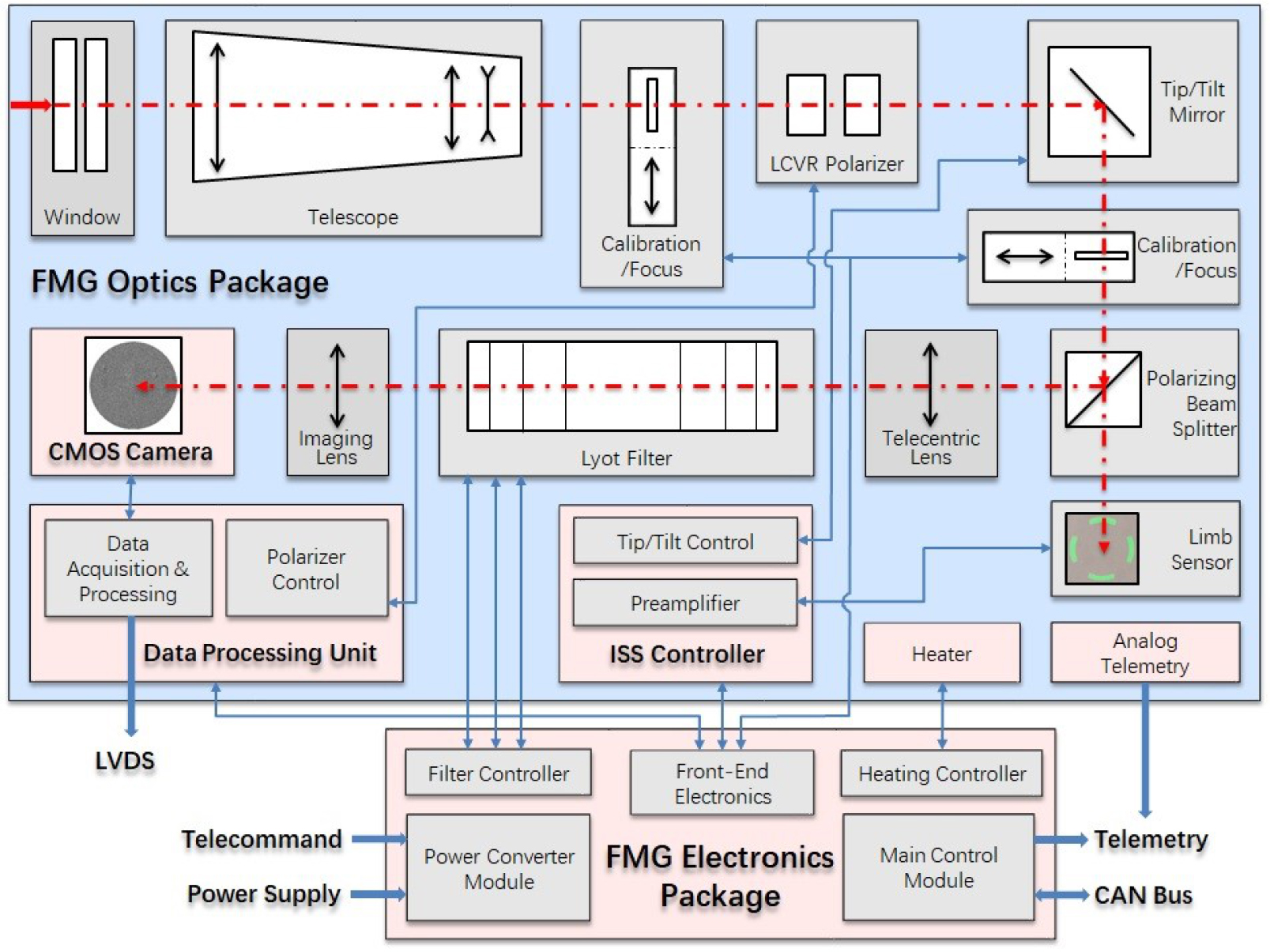
Fig. 1 Optical and electronic sketch of the FMG.
Download figure:
Standard image2.1. The Imaging Optics in the FOP
2.1.1. Optical design overview
In the FMG, the pixel number of the imaging detector is 4096 × 4096, with a pixel size of 12.8 μm × 12.8 μm. According to the requirements of the spatial resolution and field of view, the main parameters of the optical system are determined, and these can be found in Table 1.
Figure 2 illustrates the structure of the optical system. The optical system has external dimensions of 900 mm × 400 mm × 180 mm. It consists of a Front Window Filter, a Telescopic System, two Focus Wheels, a Polarimeter, an Image Stabilization System (ISS), a Beam Splitter, a Telecentric Lens, Birefringent filters, an Imaging Lens and an Image Detector.
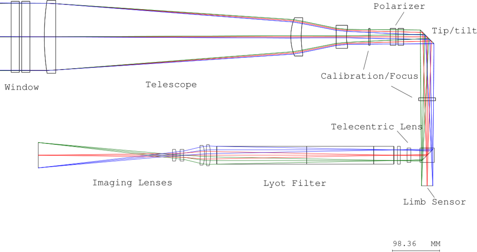
Fig. 2 The FMG optical system design scheme.
Download figure:
Standard imageFigure 3 shows the optical performance of the FMG. From the Modulation Transfer Function (MTF) and the aberration curve, one can see that the designed optical transfer function reaches the diffraction limit (1.22λ/D=0.957''), and the received spots in each field are smaller than the airy spots. The distortion in the whole field of view is better than 0.5%, which meets the design requirements. The cut-off frequency of the optical lens is higher than the Nyquist frequency of the detector. Thus, the optical performance matches the FMG design requirement, i.e., better than 1'' (the diffraction limit resolution). Regarding the image quality degradation due to some unavoidable system-wide aberrations, the spatial resolution of the finally integrated FMG will be 1.5'' (see Table 1).
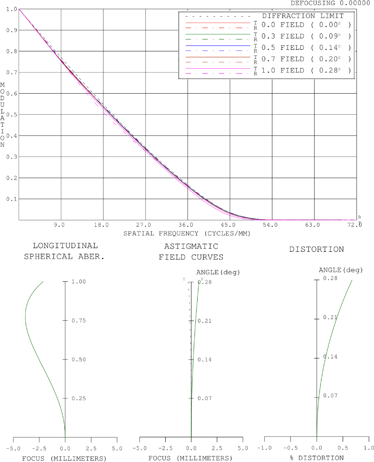
Fig. 3 Optical performance of the FMG (MTF and aberration curve).
Download figure:
Standard imageFinally, through the combination of the two wheels, 12-gear focal adjustment and calibration can be realized.
2.2. Polarimeter
2.2.1. Front window filter
The front window filter consists of two plates with a thickness of 17 mm, made from fused silica material. There are three kinds of film on the front window filter: the ultraviolet cut-off film, the narrow band filter film (bandwidth 532.42±5 nm) and the infrared reflection film.
In order to eliminate the ghost generated by the two window plates, a new wedge-plate for the window has been designed, as depicted in Figure 4. The wedge angle of each plate is 20', the second plate rotates along the X-axis with a value of 20' relative to the first plate and the machining accuracy of the wedge-plate is ±5''. When assembled, the relative rotation positions of the two plates along the Z-axis should be adjusted so that the light spot is located in the center of the detector. This scheme can eliminate the ghost in the field of view.
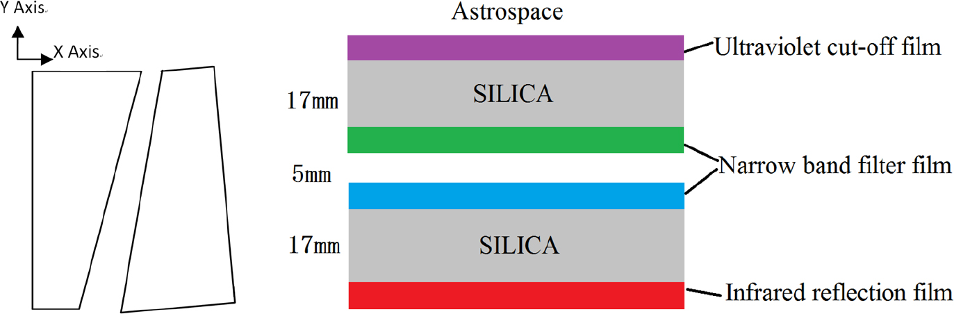
Fig. 4 Schematic diagram of the substrate material and film design of the window.
Download figure:
Standard image2.2.2. Focus and calibration wheels
Two focus and calibration wheels are set in the system, and each wheel contains six hole sites, including three plates with different thicknesses, one polarizer, one calibration lens, and one hole or baffle. The lens and plate parameters are listed in Table 2.
Table 2. Parameters Describing the Focus and Calibration Wheels
| Focus plates (JGS1) | Calibration lens | |||||
|---|---|---|---|---|---|---|
| Focus and calibration wheels 1 | 9 mm | 6 mm | 3 mm | Hole | Calibration lens 1 f = 246.5 mm (6 mm length) | Polarizing plate 1 |
| Focus and calibration wheels 2 | 5 mm | 4 mm | 3 mm | Baffle | Calibration lens 2 f = 211.9 mm (6 mm length) | Polarizing plate 2 |
In the working mode, the focus plates with different thicknesses can be selected from the two wheels to achieve 12 gears for focal adjustment. The thickness interval of the focus plates is 1 mm with focal plane changes of 1.6 mm. The focal depth of the optical system is ±1.55 mm. The maximum focus adjustment is displayed in Table 3.
Table 3. Adjustment of Focus and Calibration Wheels
| Gears | Focus adjustment | Focus length |
|---|---|---|
| Position 1 (thickness 3 mm) | –9.3 mm | 5180.27 mm |
| Position 7 (thickness 9 mm)Initial position | 0 | 5355.76 mm |
| Position 12 (thickness 14 mm) | +8.2 mm | 5511.36 mm |
In calibration mode, by rotating the two calibration lenses into the optical path, the pupil at the window can be imaged on the detector. It can achieve uniform illumination on the detector during the on-orbit calibration (Fig. 5), which is further used to calibrate the wavelength shift introduced by the Lyot filter. Moreover, it can also realize the measurement of dark field and on-orbit calibration of the LCVR through the combination of hole, baffle and polarizer.
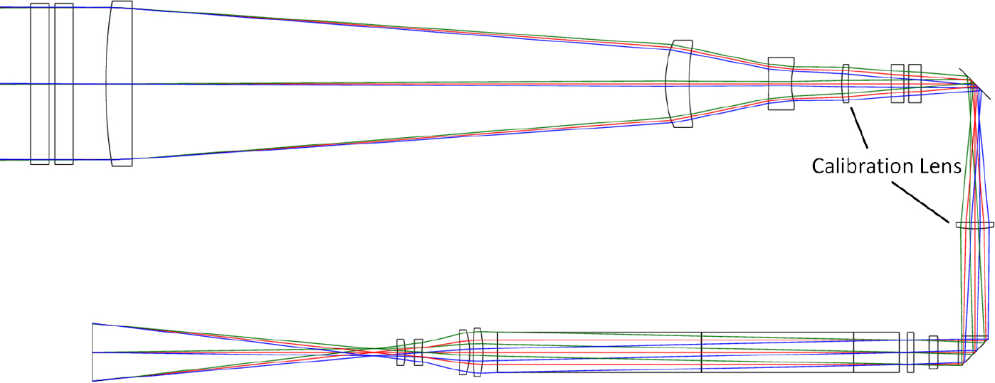
Fig. 5 FMG calibration mode diagram.
Download figure:
Standard imageThe polarimeter contains a polarization modulator and a polarizing beam splitter (PBS), as illustrated in Figure 6. The polarization modulator consists of two liquid crystal variable retarders, i.e., LCVR1 and LCVR2. The fast axis orientation of LCVR1 is the same as that of the s-polarized light direction, which is set at 0° in the vertical direction. The angle between the fast axis orientations of LCVR2 and LCVR1 is 45°. The polarization modulator is driven by adding voltages to the LCVRs to convert the desired incoming polarization from the Sun into the fixed linear polarization selected by the PBS. A full Stokes modulation mode is given to realize measurement of the Stokes I, Q, U and V parameters (see Table 4).
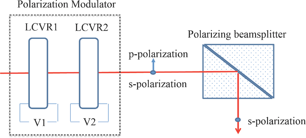
Fig. 6 Design of the polarimeter.
Download figure:
Standard imageTable 4. Full Stokes Modulation Mode of the Polarimeter
| LSVR1 | LSVR2 | Signal | ||
|---|---|---|---|---|
| Azimuth (°) | Retardation (°) | Azimuth (°) | Retardation (°) | |
| 0 | 0 | 45 | 0 | 0.5×(I+Q) |
| 0 | 0 | 45 | 180 | 0.5×(I–Q) |
| 0 | 90 | 45 | 90 | 0.5×(I+U) |
| 0 | 90 | 45 | 270 | 0.5×(I–U) |
| 0 | 0 | 45 | 90 | 0.5×(I+V) |
| 0 | 0 | 45 | 270 | 0.5×(I–V) |
The polarimeter has a fast modulation speed but no rotating mechanism, which greatly improves the polarization sensitivity. Also, a temperature control of 35 ± 0.1° C is required for the LCVRs to maintain the stability of electro-optic performance and to limit its response time to 50 ms. Furthermore, a pair of polarizers is added in the calibration wheels to calibrate the LCVRs on orbit.
2.3. Birefringent Filter
A wide-field and tunable Lyot filter is employed in FMG (Evans 1949). The seven-element Lyot filter (labeled E1 to E7) has a thickness ratio of 1:2:4:8:16:32:64. Each Lyot unit consists of eight pieces: a fused-silica spacer, a piece of calcite, a half waveplate, a piece of calcite, a quarter waveplate, a rotatable waveplate, a fused silica spacer and a polarizer. The wavelength of light traveling through the birefringent filter is tuned by a rotating half-wave plate according to the design. All of the optical components are held in optical contact by silicone oil to avoid scattered lights reflecting between their surfaces. The nominal filter full widths at half maximum (FWHMs) are shown in Table 5.
Table 5. Optical Parameters of the Birefringent Filter
| FWHM (Å) | |
|---|---|
| Blocking filter | 10 |
| Lyot element E1 | 0.11 |
| Lyot element E2 | 0.22 |
| Lyot element E3 | 0.44 |
| Lyot element E4 | 0.88 |
| Lyot element E5 | 1.76 |
| Lyot element E6 | 3.52 |
| Lyot element E7 | 7.04 |
The Lyot filter is a combination of seven-stage crystal chambers that is sealed and filled with silicone oil. Each stage contains an adjustable half waveplate for adjusting the transmission wavelength of the crystal. The use of bellows-sealed rotary feedthrough eliminates the risk of oil leakage from the rotary seal, and the rolling diaphragm seal can adjust the volume change of the silicone oil due to temperature changes (see Fig. 7). In addition, a set of oil and gas separation devices was developed to eliminate air bubbles in the silicone oil.
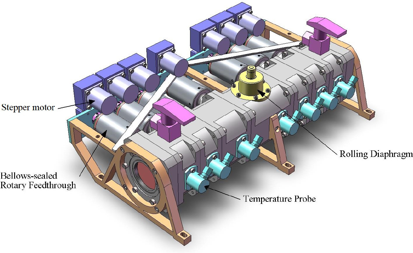
Fig. 7 Mechanical design of the FMG birefringent filter.
Download figure:
Standard imageSince the wavelength drift of the filter caused by temperature changes can be compensated for by adjusting the wavelength of each Lyot unit, automatic wavelength stabilization technology is developed (Title et al. 1976). A precise temperature probe is required to measure the temperature of each stage of the Lyot unit, and then the position of each stage of the rotating waveplate at this temperature is determined by calibration at the operating wavelength. When the temperature changes, the position of the rotating waveplate can be automatically adjusted to achieve automatic wavelength stabilization of the filter.
2.4. The Image-Stabilization System
The ISS is a closed-loop system with a tip/tilt mirror to remove jitter measured at a primary image within the FMG. It is composed of a tip/tilt mirror, a limb sensor and an image stabilization controller (see Fig. 8). The incident light is folded by the tip/tilt mirror and then split by a PBS to send the s-component light to the filters while passing the orthogonal p-component light onto the limb sensor. Four sets of detectors are positioned on the north, south, east and west limbs of the solar image, respectively. Each set consists of a redundant photodiode pair. In order to avoid the introduction of noise between the limb sensors and the electronics package, the pre-amp board is mounted inside the optics package.
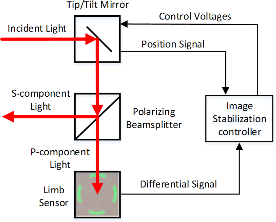
Fig. 8 Sketch of the ISS.
Download figure:
Standard imageThe tip/tilt mirror uses low-voltage piezoelectric transducer (PZT) actuators to remove errors in the observed limb position, derived as the difference between the intensity reaching opposite photodiodes. The adjustable range of the tip/tilt mirror is approximately ±10' in image space, which is employed to correct the pointing consistency error between FMG and LST, another payload on the ASO-S.
2.5. Data Acquisition and Processing System
Observations by FMG are managed by the Data Acquisition, Processing and Control System (DAPCS) during the flight. Observation commands are issued from the satellite and transferred by FEB to DAPCS. After the parameter adjustment commands are distributed by DAPCS to the corresponding components, observations will start by the command. When the data acquisition and processing are finished, scientific data will be transferred to the satellite with the instrument status being reported to FEB. DAPCS has three functions/modules and a block diagram is shown in Figure 9.
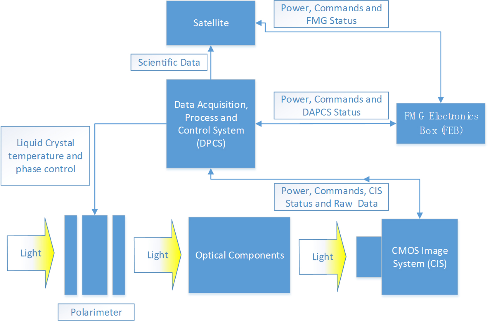
Fig. 9 Diagram of the DAPCS.
Download figure:
Standard image2.5.1. Image Detecting System (IDS)
The FMG IDS is a digital camera based on a CMOS image sensor. The IDS provides images of 4096×4096 pixels with about 10 frames per second (fps) and each pixel corresponds to a square area of 12.8 μm by 12.8 μm at the focal plane. The image is digitized to 14 bits and the maximum frame rate is approximately 12 fps under global shutter mode while the full well capacity is better than 40 Ke−.
2.5.2. Polarimeter Control Function (PCF)
The polarimeter of the FMG is designed with the LCVR. All the LCVR components must work in a constant temperature environment, and be driven by high precision pulse waves. The PCF provides an intelligent temperature controller to make sure the polarimeter's temperature variance remains within 0.1°C, and it also provides two pulse wave generators with 1 mV amplitude resolution to drive the LCVR.
2.5.3. Data Processing Function (DPF)
Data processing on orbit is managed by the DPF which is the central processing unit for observations. The satellite, FEB and IDS are connected by the DPF. DPF translates the commands from FEB, distributes them to IDS and the polarimeter, then manages the data acquisition and processing, finally reporting instrument status to FEB and transferring the scientific data to the satellite. PCF and DPF are in the same block.
The data rate of the IDS output is nearly 4 Gbps and will be processed in real time by DAPCS on orbit. The exposure of IDS and the modulation of the polarimeter must be strictly synchronized during data acquisition. Any misalignment between them will lead to observation failure. DAPCS manages the synchronization signal from IDS, and modulates the polarimeter in specific time sequences, then integrates the data from the left-handed and right-handed circular polarizations in real time.
3. FMG Electronics Box
The FMG electronic control system is composed of a main control circuit, a temperature control moving parts drive circuit and a secondary power circuit. The main control circuit takes the main control CPU as the core circuit and is responsible for the internal interface of the load and the control interface with the satellite platform. The temperature control circuit is responsible for the temperature control of the incident window and the optical box. The moving parts drive the circuit to realize image stabilization control function, automatic wave band stabilization control function and calibration/focus control function. In order to describe its schematic design more completely and clearly, the complete FMG electronics system can be divided into eight functional circuit units as follows:
- –Power supply and distribution circuit.
- –Main control circuit.
- –Active temperature control circuit.
- –Front-end electronics interface circuit.
- –Data acquisition and processing circuit.
- –Polarization analyzer circuit.
- –Image stabilization circuit.
- –Filter circuit.
The power supply and distribution circuit unit, the main control circuit unit and the active temperature control circuit unit form a hardware circuit board, which together constitute the common electronics part of the FMG electric control box. The front-end electronics interface circuit unit is a unified optimized layout of the interface to form a hardware circuit board. At the same time, the calibration/focusing circuit unit and its interface are also arranged on this circuit board, which is called the front-end electronics interface circuit board. In addition, the electronic control system of the filter forms a circuit board separately.
3.1. Power Supply and Distribution Circuit
The satellite platform distributor provides the primary power supply for FMG with a voltage of 30±3 V. The average power consumption is not less than 230 W. The power supply of the satellite platform is connected to the FMG electronic control box, and there are four directions:
- –Supply +5 V, +3.3 V, ±12 V, +24 V power to other circuit units through a DC/DC module.
- –Access to temperature control circuit.
- –Access to image stabilization electronics unit.
- –Access to data acquisition electronics unit.
The input interface circuit of the FMG primary power supply is designed in strict accordance with the design and construction specifications, with over-current protection measures. When starting up, the surge current jump slope will not be greater than 106 A s−1, and the duration will be less than 10 ms.
3.2. Main Control Circuit
The FMG main control circuit unit is mainly composed of the CPU, SDRAM, FLASH, LDO, crystal oscillator, watchdog, CAN transceiver, RS422 transceiver, analog multiplex switch, operational amplifier, AD, OC command driver and other circuits.
The main control CPU is the core component of the main control circuit. The bus communication with the satellite platform, engineering parameter telemetry, and control and management of other functional circuit units are all completed by the CPU control. The CPUs selected in this project are Loongson WH1770 and WH1771, which are 32bit based on MIPS architecture and are radiation-hardened. The company's internal numbers are respectively Loongson 1E (LS1E) and Loongson 1F (LS1F). The two CPUs adopt bridge chip mode, in which Loongson 1F is the IO bridge chip supporting Loongson 1E. The goal is to replace the field-programmable gate array (FPGA) in telemetry remote control applications in the aerospace field by integrating the telemetry remote control function interface and peripheral interface commonly applied in the aerospace field.
The main functions of the main control circuit are as follows:
- –Communication with satellite platform is realized through a CAN bus.
- –Calibration time.
- –Run FMG master control software.
- –Collect and process analog, digital and state quantities of relevant circuits, and form equipment engineering parameter package.
- –Two-way RS422 communication with data acquisition circuit unit.
- –Two-way RS422 communication with the circuit unit of image stabilization mechanism.
- –Two-way UART communication with electronic control unit of FMG optical filter.
- –Control and management of the circuit unit of the calibration/focusing mechanism.
- –Control and management of the active temperature control circuit unit.
3.3. Temperature Control Circuit Unit
FMG optical boxes and satellite decks are insulated. Temperature control of the FMG optical box includes two aspects. First, FMG is temperature-controlled in a safe mode to meet its storage temperature requirements under mission profiles such as on-orbit and off-orbit operation, and sudden satellite failure. The second aspect is the temperature control of FMG under the normal working state when it is powered up alone, so as to meet its working temperature requirements.
The temperature acquisition and processing circuit of the active temperature control, the driving circuit of the heating chip and the control algorithm of the active temperature control are completed in the active temperature control electronics unit of the FMG electric control box.
The control unit of the temperature control circuit is the main control CPU. In the application program of the main control CPU, the thermal control task subroutine is specially designed, to realize the heating loop open loop parameter setting (open loop heating/no heating, closed loop target temperature), main or backup thermal sensitivity selection, target temperature setting and other functions.
3.4. Front-end Electronics Interface Circuit Unit
Front-end electronics refers to the electronic control part placed in the FMG optical box, including the data acquisition electronics system of the FMG optical box, image stabilization electronics and calibration/focusing electronics system. A front-end electronics interface circuit board is designed in the FMG electric control box for docking with the electronics unit in the optical box. The front-end electronics interface circuit mainly includes the following contents:
- –Data acquisition box power supply and extended remote command interface.
- –Data acquisition box command/state and second pulse interface.
- –Data acquisition box extended analog telemetry interface.
- –Image stabilization box power supply interface.
- –Image stabilization box command/state interface.
- –Image stabilization box extended analog telemetry interface.
- –Calibration/focusing electric control circuit and its interface.
4. The Harness
The FMG harness includes internal cables and external cables. The internal cables consist of 10 cables including the internal cables of the FOP and the cables between the FOP and FEB. The power supply and control of focal box, image stabilization of optical box, birefringent filter control and thermal control are completed through the FEB. Meanwhile, there are eight external cables, among which six cables located in the electric control box are mainly utilized to operate the power supply, telemetry, remote control, CAN bus and other functions, and the other two cables located in the optical box are mainly used to accomplish telemetry of analog data and scientific data transmission.
5. The thermal control system
The thermal control system of the FMG is used to maintain the survival, normal operation and CMOS purification of FMG in orbit. The three functions above share the same heating system and guarantee the different ranges of temperature by setting different temperature thresholds.
The survival mode of FOP, which generally occurs in the early stage of orbit when the satellite lacks sufficient power supply, uses the minimum power necessary to avoid damage to the FMG. The thermal control unit of FEB is directly powered by the satellite to maintain the FOP heater at survival temperature.
The temperature control system operates entirely to ensure the temperature of the FOP is 22± 2°C when FOP is in normal operating mode.
The CMOS temperature control is set up individually and its operating temperature is −30 – 10°C. Heat generated by the CMOS is transferred to the radiator which is specially set via a heat pipe to ensure its correct operating temperature. The purification mode is where the CMOS needs to be heated to +20°C to remove pollution on the CMOS target plane.
6. Test observation of FMG prototype
We carried out test observations with the FMG prototype from 2019 Jan. 28 to Mar. 22 at Huairou Solar Observing Station (HSOS). There are two main purposes for the test observations. On one hand, we would like to test the overall performance of the FMG after combining the ISS, the LVCR polarimeter and the CMOS detector as well as the birefringent filter with the automatic wavelength stabilization technique, as this is the first application of a solar magnetograph in China. On the other hand, the ground and on-orbit calibration items of the whole system, e.g., on-orbit focusing, dark and flat field calibration, polarization calibration, wavelength calibration, etc., will be tested.
The FMG prototype is firstly placed in a super-clean laboratory for about 3 d to carry out the polarization calibration and measurement of the transmission profile of the filter with the help of a dye laser, a collimator and the polarization calibration unit. The details of FMG calibration equipment and the calibration results will be reported in subsequent papers. Thereafter, the FMG prototype is installed on the equatorial platform at HSOS to finish the calibration of the other items and to observe the full-disk solar magnetic field. In Figure 10(a), one can clearly see the optical packages (blackbox) of the FMG mounted on the white box of the equatorial platform. Figure 10(b) displays a picture of the FMG prototype pointing at the Sun. The pointing and tracking of the Sun are realized by the equatorial platform, and this function will be replaced by the ASO-S satellite platform once the FMG is launched into orbit.
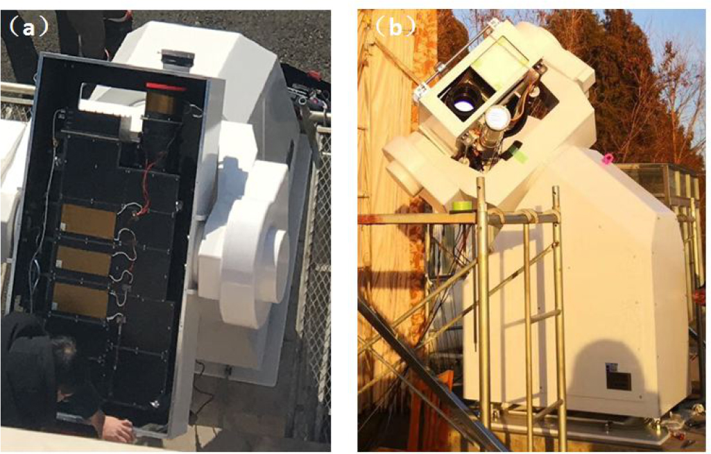
Fig. 10 Top (a) and side (b) views of the FMG prototype installed on the equatorial platform at HSOS.
Download figure:
Standard imageGenerally speaking, three elements must be satisfied in a solar magnetograph. Firstly, we need the detector and Lyot filter to obtain a narrow band solar image. Secondly, the Lyot filter must work at the selected wavelength position of the working line, which is −0.08 Å from the line center of the Fe i 532.4 nm line for the FMG. Lastly, the polarization analyzer is needed to obtain the Stokes I, Q, U and V parameters. The ISS is employed so as to avoid the influence of the solar image jitter caused by the satellite or the equatorial platform and improve the spatial resolution of the Stokes images, which generally have 150 frames of integration to increase the polarization sensitivity. It is extremely important that the transmission profile of the Lyot filter be stabilized at the selected wavelength position, otherwise the vector magnetic field calibration will become more and more complex because the calibration coefficient varies with wavelength position. In the following subsection, we describe the performance of the ISS and the wavelength stability of the Lyot filter, followed by a subsection featuring the test results from the FMG prototype.
6.1. Performance of the ISS
Figure 11 compares the variation of the solar disk center under three different conditions. If both the guiding system and ISS are off, one can find that the largest shift or jitter of the solar disk center is about 15'' within about 30 minutes. The shifts come from installation errors of the polar axis on the equatorial platform. If we turn on the guiding system, the value declines a lot and lies in the range of 0–4'' with a root mean square (RMS) value of 0.96'', as depicted in Figure 11(b). Once the guiding system is off and the ISS is on, we can see the shift of the disk-center falls between 0 and 2.16'' (Fig. 11(c)), indicating that the ISS is working correctly, otherwise it should be almost the same as the result in Figure 11(a). The corresponding RMS value is 0.389'' within 30 min, even lower than the above case with only the guiding system on. Note that we possibly cannot achieve the value of 0.25'' as mentioned in Table 1 due to the influence of the seeing effect caused by the Earth's atmosphere.
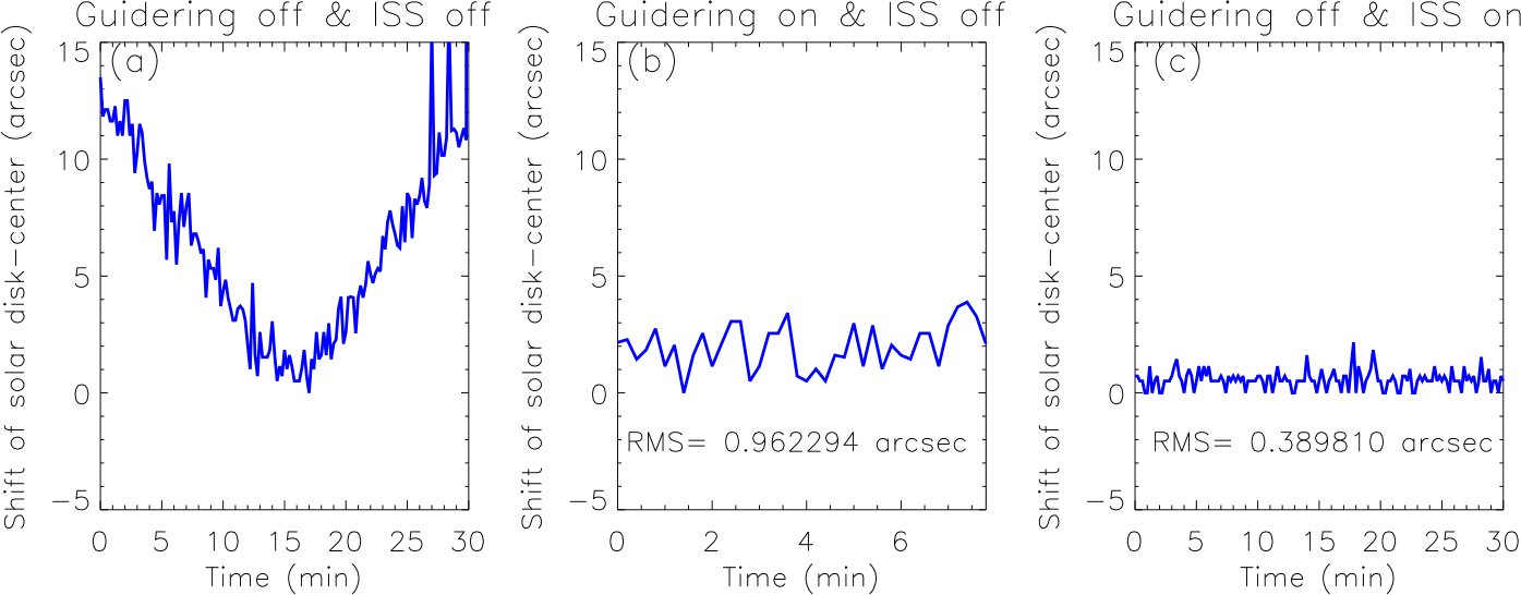
Fig. 11 Variation of the solar disk center with time at different configurations. (a) The value with both of the guiding system and ISS off. (b) The value with the guiding system on and ISS off. (c) The value with the guiding system off and ISS on.
Download figure:
Standard image6.2. Performance of the Wavelength Stability of the Lyot filter
Different from the accurate temperature control system generally used in the Lyot filter on the ground, the Lyot filter of FMG employs an entirely new technology, named automatic wavelength stabilization technique. The excellent performance of the Lyot filter with the new technique can be ascertained in Table 6. It is found that the relative drift in the peak position of the Lyot filter's transmission profile was maintained at between 0.005 and 0.027 Å, with a peak-to-peak value of 0.022 Å even if the temperature of the filter already changed by 9° C (from 14.7 to 23.7° C). The working temperature of FMG is 22± 2° C, which is much smaller than the temperature variation in the test observation. So, the peak-to-peak shift of the Lyot filter's transmission profile meets the requirement for FMG, which is 0.02 Å. The peak position of the Lyot filter's transmission profile in the above analysis is derived from the line center of the Fe i 532.4 nm working line when applying the Gaussian fitting method. The working line is obtained when we tune the Lyot filter from the blue wing to the red wing with a step of 0.02 Å. In order to overcome the influence of the small-scale solar velocity, we take the average of the scanned spectral profiles in a quiet Sun region near the solar disk center.
Table 6. Wavelength Stability of the Lyot Filter at Different Temperatures and Days
| Date | Temperature of the filter (°C) | Position of line center (Å) |
|---|---|---|
| 2019 Feb. 01 | 14.7 | 0.005 |
| 2019 Feb. 01 | 18.27 | 0.022 |
| 2019 Feb. 04 | 23.7 | 0.027 |
| 2019 Feb. 05 | 19.18 | 0.026 |
| 2019 Feb. 11 | 14.7 | 0.006 |
6.3. Test Observation Results
As mentioned above, the FMG must satisfy three elements to measure solar magnetic fields, i.e., a solar monochromatic image, a suitable wavelength position of the Lyot filter and a polarimeter to derive the Stokes I, Q, U and V parameters. Figure 12(a) shows a monochromatic image of the Sun taken by the FMG prototype on 2019 Mar. 6. The image has been corrected for dark and flatfield, and the sunspot in NOAA Active Region (AR) 12734 can be identifies in the image. The solid line in Figure 13 represents the scanned spectral profile of the Fe i 532.4 nm line taken by tuning the Lyot filter from –1 Å to +1 Å with a step of 0.04 Å. The scanned solar spectrum is very glossy and does not have any discontinuity points, indicating that the tuning function of the Lyot filter works well. The dashed line in Figure 13 refers to the transmission profile of the Lyot filter, which is calibrated in the laboratory with a dye laser. The FWHM of the Lyot filter is 0.106 Å and its out-of-band stray light is 21.3%. The peak position of the transmission profile marks the working wavelength position of the Lyot filter during the measurement of solar polarization, which is at –0.08 Å from the line center of the Fe i 532.4 nm line. With the LVCR polarimeter, we took the polarization observation at the working wavelength position and demodulated the Stokes V/I images as displayed in Figure 12(b). From Figure 12(b), the positive and negative polarities of the full-disk longitudinal magnetic field corresponding to the monochromatic image in Figure 12(a) can be found. Also, one can see much stronger V/I signals in the sunspot, with brighter or darker values than in nearby quiet-Sun regions. Here, the crosstalk from Stokes I to V has been corrected when we plot the image. Note that the arc-shaped stripes in Stokes V/I images originate from the crosstalk of the eight readout channels of the CMOS detector, and we are going to try our best to reduce the effect by screening the CMOS detector and optimizing its performance parameters in the future. More details on the FMG data production process can be found in Su et al. (2019).
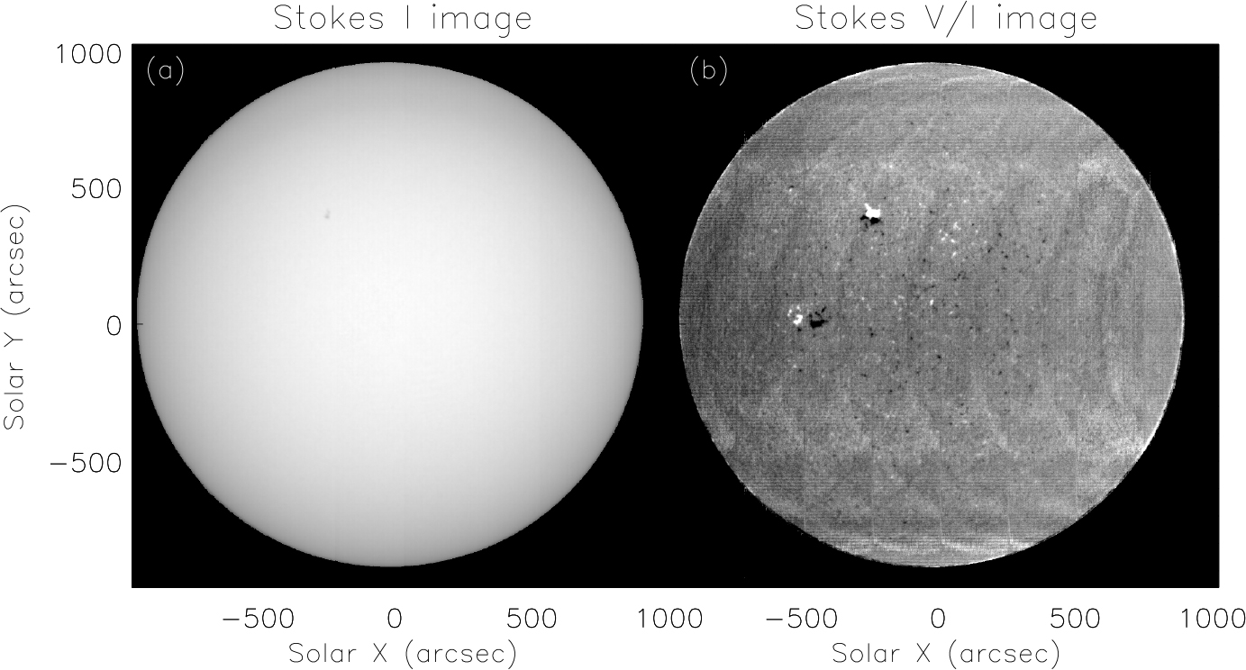
Fig. 12 Monochromatic (a) and Stokes V/I image (b) taken by the FMG on 2019 Mar. 6.
Download figure:
Standard image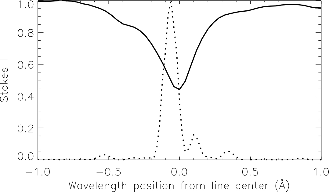
Fig. 13 Scanned spectral profile of the Fe i 532.4 nm line (solid line) and the transmission profile of the Lyot filter (dashed line). The peak position of the transmission profiles marks the wavelength position of the Stokes V/I image shown in Fig. 12(b).
Download figure:
Standard image7. Conclusions
We have finished the design of the FMG payload. By test observations, we verify the functions of the FMG. They satisfy the design requirements. We also test some technical parameters and find that most of them meet the requirements. But, there are still some drawbacks, such as the detector uniformity, frame rate, etc. We will concentrate on these aspects in future development work. In addition, space environment experiments will be carried out in the near future.
Acknowledgements
The authors would like to thank the referee for valuable comments. Moreover, we sincerely thank the following institutes for their help and support during the development of FMG. They are: China Aerospace Science and Technology Corporation, the NO.771 Institute; China Academy of Engineering Physics; Changchun Institute of Optics, Fine Mechanics and Physics, CAS; National Space Science Center, CAS; Shanghai Engineering Center for Microsatellites, CAS; and Purple Mountain Observatory, CAS. We are also grateful to staff and students at HSOS for their help during the test observations of the FMG prototype. This research work is supported by Grants: XDA15320102, 11427901 and XDA15052200.