
Abstract
The shock wave initiation of ultra-fast chemical reactions in inorganic powder mixtures requires the reactants to be blended within the shock front or shortly behind it. As such, the details of particle deformation are crucial to understanding the sequence of events leading up to the shock initiation of these systems. It is known that the initial configuration of a powder (i.e. the mixture composition and particle morphology) can have a significant effect on the degree of mixing that is achieved under shock wave loading. However, it is difficult to fully resolve this mixing behaviour in shock compression experiments due to the time and length scales involved. In this work, the shock wave deformation and mixing of six distinct Ni/Al powders are studied at the particle level using finite element simulation. Attention is focused on the Ni/Al interfaces that are formed since overall mixture reactivity depends on the specific amount of reactant interfacial area and on conditions induced at those interfaces. The analysis reveals (i) a rank ordering of the powders based on reactant interfacial area formation, (ii) a scaling relation for the rate of Ni/Al interface production and (iii) the distributed nature of Ni/Al interface temperature and dislocation density over a range of shock stress. Finally, it is shown that particle velocity differentials tend to develop across Ni/Al interfaces when the compacted powders are reshocked by reflection waves. The velocity differentials stem from the heterogeneity of the aggregates and are hypothesized to drive fragmentation processes that enable ultra-fast reactions on a sub-microsecond time scale.
Export citation and abstract BibTeX RIS
1. Introduction
It has been demonstrated that shock wave loading can be used to initiate ultra-fast chemical reactions in micrometre-scale inorganic powder mixtures [1–7]. The distinguishing feature of these reactions is their speed. They are detected in real-time measurements of the shock-compressed state, which indicates significant product yields within the shock front or closely behind it. Given that the shock rise time in these powders is ∼100 ns and the duration of the high-pressure state is ∼1 µs, the reaction mechanism must operate on a sub-microsecond time scale. These material systems are heterogeneous at the level of individual particles and must be mixed (i.e. blended at the atomic level) to undergo reaction in the bulk. Thus, reactions are limited by the rate of mass mixing. Conventional thermally activated diffusion rates are too slow to explain ultra-fast, shock-induced reactions among micrometre-scale particles. Therefore, it is thought that mechanical deformation at the particle level (and below) plays an important role in achieving the mixing rates required for the shock initiation of these powders.
The details of particle-level shock deformation are influenced by the initial configuration of the powder mixture. In this context, initial configuration refers to the molar composition of the mixture, the sizes and shapes of the constituent particles and the spatial arrangement of the phases/particles. Changes in initial configuration tend to alter mixing conditions, which in turn influence energy release characteristics and shock ignition thresholds. Achieving real-time resolution of the particle-level deformation that leads up to shock ignition is beyond the capability of current experimental methods. Therefore, we use finite element (FE) simulation to study the particle-level responses of several powder configurations under shock wave loading. The Ni/Al powder system is selected for study because (i) there is a body of experimental data on powder configurations that do and do not undergo shock ignition and (ii) the highly exothermic nature of intermetallic-forming reactions in the Ni/Al system renders these powders attractive to reactive materials applications.
In previous work, we focused on simulating the shock responses of mono-sized spherical Ni/Al powders for the purposes of model validation and preliminary investigation [8]. In this work, our analysis is extended to two new mixture classes: powders that display a bimodal particle size distribution (larger Al particles + smaller Ni particles) and powders composed of composite particles (Ni-coated Al particles). This allows for investigation of the effects of relative particle size and phase arrangement. It is noted that the macroscopic rate of reaction in a heterogeneous multi-phase system is not a unique function of pressure, temperature, strain, etc. Rather, reactions occur in discrete zones, the extent of which depends on the interfacial area between the reactants. Therefore, attention is focused on the Ni/Al interfaces that are formed during shock wave loading. In each powder, we compute the specific amount of Ni/Al interfacial area, the rate of Ni/Al interface growth and the distributed nature of interface temperature and dislocation density, all as functions of shock strength (stress wave amplitude). Finally, it is demonstrated that particle velocity differentials tend to develop across Ni/Al interfaces when the compacted powders are reshocked by reflection waves. Assuming a model of grain fragmentation driven by these local velocity fluctuations, it is shown that the shock ignition threshold predicted for a specific powder is in agreement with the experimentally observed threshold.
2. Background
The study of ultra-fast chemical reactions in shock-loading experiments requires the use of time-resolved measurements. Manifestations of such reactions may take the form of shock wave speeds or stress wave amplitudes that are higher than expected, owing to the heat of reaction and/or production of new phases with distinct properties [5, 9]. In order for such deviations from the inert mixture response to be detected in experiments with reasonable confidence, the overall degree of conversion during the shock wave loading must be significant, e.g. greater than 30% [10]. Time-resolved plate impact experiments have been used to investigate shock-induced reactions in a set of Ni/Al powder mixtures [3, 4, 7, 11, 12]. The results of these experiments are briefly summarized to identify the subset of Ni/Al powders that have been shock initiated and the associated initiation threshold loading conditions.
The first experimental observations of ultra-fast reactions in the Ni/Al powder system are due to Bennett et al [3]. In these plate impact experiments, planar shock waves were propagated in spherical Ni/Al powder mixtures (5 µm Ni + 20 µm Al, 55% TMD). For stainless steel flyer velocities below ∼1.075 km s−1, pressures recorded in the incident and reflected waves fell in line with pressures expected for an inert powder. For all shots above ∼1.075 km s−1, excess pressures of ∼5 GPa were recorded in the reflected waves and taken as evidence of ultra-fast reaction. The occurrence of reaction was confirmed by microscopic analysis of the recovered specimens, which revealed full conversion of the Al phase. The product phase was predominantly NiAl3. These results were corroborated by a separate set of experiments (involving the same powder configuration) that were performed on a different gas gun [4]. The experiments of Yang et al [4] demonstrated that the structure of the shock wave (i.e. the shock ring-up process) has an influence on whether or not shock ignition is achieved. The key parameter that controlled whether or not ultra-fast reactions were initiated was the stress jump upon wave reflection, instead of peak stress amplitude. The critical stress jump that was required to initiate the powder under study was ∼14 GPa. This criterion indicates that the reaction mechanism is tied to the details of particle deformation and mixing, and not just the amount of energy deposited in the mixture.
Three distinct equivolumetric Ni/Al powder mixtures were considered in the plate impact experiments of Eakins and Thadhani [7, 11, 12]. The powders were composed of (i) micrometre-scale spherical Ni + Al powders (−325 mesh, 60% TMD), (ii) flaky Ni + spherical Al powders (−325 mesh, 45% TMD) and (iii) nanoscale spherical Ni + Al powders (∼100 nm, 40% TMD). The micrometre- and nanoscale powders remained inert for stress wave amplitudes of up to 6 GPa. However, the flaky Ni mixture displayed higher-than-expected shock wave speeds for shock stresses greater than ∼3.5 GPa, which is indicative of reaction. In this case, reaction appears to have occurred in the incident wave prior to any wave reflection. The differing reactivity of these powders was attributed to differences in particle-level mixing conditions. The micrometre-scale powders remained inert because the interior regions of the Ni and Al particles remained separated by large distances, whereas incomplete densification in the nanoscale powders limited the amount of contact between the Ni and Al phases. In the case of the flaky Ni mixture, the spreading of Al particles over the thin Ni flakes produced large interfacial areas between the constituents and reduced the mass transport length required for significant product yields. Thus, particle size and morphology can have a significant effect on the deformation and mixing of the particles under shock loading and an influence on whether or not shock ignition is achieved.
Finally, a set of plate impact experiments that were performed on a composite Ni/Al powder mixture (micrometre-scale Al particles with Ni coatings, 65% TMD) revealed a critical threshold above which recovery micrographs show an abrupt change in constituent mixing behaviour [13]. For stainless steel flyer velocities below 0.8 km s−1, the particle deformations appear relatively quiescent. Above 0.8 km s−1, there is a loss of regularity in the packing arrangement of the particles and the appearance of surface instabilities at the material interfaces. These experiments did not provide evidence of ultra-fast reactions in these powders, as time-resolved diagnostics were not used. However, the enhanced mixing that is observed above a critical loading condition provides some insight into flow features (e.g. surface instabilities, shear localization, turbulent flow) that may be precursory to ultra-fast reactions.
Direct numerical simulation has proven useful for analysing the dynamic responses of heterogeneous material systems at intermediate length scales. For example, the FE method has been used to study particle-level responses in a variety of powder systems under shock wave loading [8, 14–28]. The discrete element (DE) method has also been useful for studying particle velocity dispersions in shocked mixtures [29] and fragmentation processes in multi-phase shear bands [30]. Work specific to the Ni/Al powder system includes the aforementioned DE calculations [29, 30], the FE calculations of Eakins and Thadhani [24, 25], which considered powder morphologies imported from digitized micrographs, and our previous FE calculations on spherical powders [8], which incorporated a rate-dependent model of particle flow stress and microstructure evolution. In our previous work, it was shown that our numerical model is in agreement with a number of measurements obtained from the corresponding experimental powder. This provides a measure of confidence in extending our model to a new set of powders that are yet to be studied using direct numerical simulation.
3. Powder mixtures
The initial configuration of a powder mixture is determined by its composition, the constituent particle morphologies and the spatial arrangement of the phases. The powder mixtures that have been selected for study are given in table 1. The selected powders have been grouped into classes (E, B and C). Mixture class E contains two variants of an elemental powder with equal-sized spherical Ni and Al particles. Mixture class B contains two variants of an elemental powder that has a bimodal particle size distribution (larger spherical Al particles + smaller spherical Ni particles). Mixture class C contains two variants of a composite powder, i.e. spherical Al particles with Ni coatings. Mixture class B allows for investigation of the effects of relative particle size, whereas mixture class C introduces a different type of phase arrangement. The powders have been selected to investigate a set of experimental powders and to explore the role of initial configuration in the deformation and mixing of a system with fixed composition. Mixture B1 corresponds to the experimental powder that displayed evidence of shock-induced reactions for stress jumps of sufficient magnitude [3, 4], whereas mixture C1 corresponds to the experimental powder that displayed evidence of flow instability above a critical impact threshold [13]. Mixtures E5 and E20 are the equivolumetric powders that were investigated in our previous work [8]. Mixtures B2 and C2 were selected to extend our study of the equivolumetric system to bimodal powders and composite particle powders. Thus, four distinct powder configurations (E5, E20, B2 and C2) are investigated within the equivolumetric Ni/Al system that is 60% dense. The flaky Ni mixture that showed evidence of shock ignition [7] was considered in previous simulation work [25] and is not reconsidered here.
Table 1. Simulated Ni/Al powder mixtures.
| Mix. | Molar composition | Vol. ratio (Ni : Al) | % TMD | Particle shape | Mean particle size (µm) | |
|---|---|---|---|---|---|---|
| Ni | Al | |||||
| E5 | 1.5 Ni + 1 Al | 1 | 60 | spherical | 5 | 5 |
| E20 | 1.5 Ni + 1 Al | 1 | 60 | — | 20 | 20 |
| B1 | 2.6 Ni + 1 Al | 1.7 | 55 | — | 5 | 20 |
| B2 | 1.5 Ni + 1 Al | 1 | 60 | — | 5 | 20 |
| C1 | 1.8 Ni + 1 Al | 1.2 | 65 | composite | 60 (outer dia.) | |
| C2 | 1.5 Ni + 1 Al | 1 | 60 | — | 60 (outer dia.) | |
4. Methods
Shock wave loading of the discrete powders was simulated using the Eulerian FE code RAVEN [33]. RAVEN is a 2D multi-material code in which operator splitting is used to decouple and solve the governing equations in a sequential manner. The powders were reconstructed using a random sequential addition procedure [34], which was described earlier [8]. Samples generated in this manner are statistical volume elements (SVEs); therefore, multiple samples of each powder were simulated to build up statistical descriptions of material response. The simulations were performed on powders rendered in two dimensions (under plane strain) with all material interfaces being perfectly bonded. The assumption of perfectly bonded interfaces is partially justified by the frictional barriers created under high pressure. At peak shock pressure, material in the vicinity of an interface will undergo plastic flow before sliding on the interface. However, near the leading edge of the shock, where the confining pressure is still low, this assumption likely does not hold. Although full 3D calculations are certainly desirable, 2D calculations have been shown to offer considerable value in understanding particle-level shock deformation and morphology effects, and are significantly more tractable. Finally, this work is meant to serve as a baseline study of the shock deformation and mixing of various Ni/Al powder configurations. As such, chemical reactions among the phases are not modelled.
4.1. Boundary value problem and meshing
The boundary value problem is analogous to a miniature plate impact experiment (see section 5 for illustration). The powder sample is placed between a flyer plate and a backer plate. The plates are made of OFHC Cu for mixture class E and 304 stainless steel for mixture classes B and C, so as to be consistent with the experiments. The shock wave is generated by assigning an initial velocity to the flyer plate, which impacts the powder. Rigid frictionless walls are located at the top and bottom surfaces of the volume element. Transmitting boundary conditions are utilized at the left- and right-hand surfaces of the volume element, which allow plate material to flow across the boundary and waves to pass through the boundary with minimal reflection. The powders are compacted by an incident wave and reshocked by the wave reflected from the backer plate. The simulation is run until the reflected shock wave reaches the flyer plate.
The powders were meshed using uniform Eulerian grids. Appropriate mesh sizes were determined by performing a mesh sensitivity study, which considered profiles of longitudinal stress, flow stress (von Mises effective stress) and temperature taken from longitudinal sections of the fully compacted powders, just prior to reflection. The mesh size for each powder was refined until further reductions in size yielded only small changes in the results. The mesh lengths that were determined from this study are as follows: 0.5 µm for mixtures E5, B1 and B2, 1.2 µm for mixture E20, and 2.0 µm for mixtures C1 and C2. These mesh sizes are similar to those used in earlier computational studies of Ni/Al particle systems [24, 25]. However, it is worth noting that the present calculations can involve strain localization, which prevents true convergence on any mesh that does not regularize the solution in a sufficient way.
4.2. Constitutive models
The dynamic conditions involved in the shock compression of porous powder mixtures necessitate careful selection of constitutive models for the coupled thermal–mechanical responses of the particles. In this work, the Ni/Al powders are subjected to stress jumps of up to ∼10 GPa from the initial state. These loading conditions produce strain rates of up to ∼108 s−1 in the shock front and temperatures up to and beyond the melting points of the constituents. A set of constitutive models was selected to address the shock deformation of the Ni and Al particles in our previous work [8]. A brief description of this framework is given below.
The deviatoric stress–strain responses of the particles are described using a physically based macroscopic model of high-strain-rate viscoplasticity [35, 36]. The model is based on the generation and glide of dislocations, accounting for the effects of pressure, temperature, strain rate and microstructure evolution under shock wave loading. Here, the kinetics of dislocation glide are framed in terms of thermally activated obstacle bypassing at stresses below the mechanical threshold and phonon-damped motions at higher stresses. The mobile and immobile dislocation densities are distinguished and taken as evolving internal state variables. Their evolution is governed by the stress-dependent nucleation, multiplication, annihilation and trapping of dislocation segments. As in our previous work [8], the heterogeneous nucleation of dislocations from sources is included and the homogeneous nucleation of dislocations within the lattice is neglected. The static strength of the material is related to the square root of the total dislocation density using the Taylor relation. Model parameter values for Ni and Al have been reported previously [36]. The volumetric responses of the particles are modelled using the Mie-Gruneisen equation of state (parameters given in table 2).
Table 2. Material properties (at standard temperature and pressure).
| Ni | Al | ||
|---|---|---|---|
| Mass density—ρ0 | g cm−3 | 8.875 | 2.712 |
| Bulk wave speed—c0 | km s−1 | 4.59 | 5.38 |
| Linear coefficient of shock wave speed—particle speed relation—s1 | 1.44 | 1.34 | |
| Gruneisen parameter—Γ0 | 1.8 | 2.2 | |
| Heat capacity—c | J g−1 K−1 | 0.460 | 0.904 |
| Thermal conductivity—κ | W m−1 K−1 | 90.9 | 222 |
| Melt temperature—Tm0 | K | 1728 | 926 |
| Pressure sensitivity of melt temperature—∂Tm/∂p | K GPa−1 | 12.6 | 41.2 |
| Latent heat of fusion—Δhfus | J g−1 | 306 | 390 |
| Melt viscosity—η | Pa s | 2 × 10⁻⁴ | 2 × 10⁻⁴ |
| Free surface energy—γs | J mm−2 | 1.756 × 10⁻⁶ | 0.860 × 10⁻⁶ |
One of the main conclusions of our previous work [8] was that the rate-sensitivity of particle flow stress can have a significant effect on predicted flow morphologies in the Ni/Al system, at least for intermediate stress wave amplitudes. This follows from the pronounced increase in the flow stress of fcc metals at strain rates above ∼105 s−1. In our previous work, the shock deformation of an experimental powder (mixture E20) was separately simulated using the above model of viscoplasticity and a conventional rate-independent strength model (i.e. the Steinberg–Guinan model). When compared to the experimental recovery specimen, the viscoplastic model appeared to provide a more realistic description of the deformed particle morphology. Specifically, the highly fluidic deformation that was predicted for the Ni phase, when using the rate-independent model, was not observed in the recovery specimen. The higher flow stresses and smaller plastic strains that are predicted by the viscoplastic model stem from the rate-dependent formulation, which allows effective stress states that fall beyond the current yield surface. The magnitude of this deviation determines the plastic strain rate and the subsequent time-dependent relaxation of the material. This is in sharp contrast to the rate-independent case, where plastic strain increments are calculated according to a consistency condition that keeps the effective stress state on the yield surface.
Temperatures are calculated as
where e is the internal energy per unit mass, ec is the cold compression energy, em is the melting point energy, Tm is the melt temperature, c is the heat capacity and Δhfus is the latent heat of fusion. It is assumed that the heat capacity of each phase is constant and that all inelastic work is converted to heat. The melt energy is expressed as em = ec + cTm and the melt temperature is a simple function of pressure, i.e. Tm = Tm0 + (∂Tm/∂p)p. As shown above, the solid-to-liquid phase transformation accounts for the latent heat of fusion. Furthermore, the static strength of a material is reduced to zero with the progress of melting. Upon full melting, the Ni and Al phases are modelled as viscous Newtonian fluids. Heat conduction is modelled using Fourier's law, wherein the thermal conductivity of each phase is assumed constant. Relevant material properties are given in table 2.
The focus of this work is to resolve the shock responses of various configurations of a given material system to study how variations in mesoscale structure lead to differences in deformation and mixing behaviour. In addition to mesoscale structure, the shock-induced mixing and reactivity of a powder is influenced by differences in the properties of the constituents [5, 9]. For example, systems composed of phases with similar mass densities and similar initial yield strengths (Ni/Ti, Ti/Si) tend to be more prone to shock ignition as compared to those with larger disparities in such properties (Mo/Si, Ni/Al), for a given mesoscale structure [11]. Although our study is somewhat orthogonal to this point, it is worth mentioning that the Ni/Al system displays significant differences in mass density, heat capacity, thermal diffusivity, melting temperature and flow strength, which contribute to the pronounced heterogeneity of thermal and mechanical responses under shock wave loading.
5. Results
The powder mixtures were impacted with flyer plates assigned initial velocities in the range of 0.6–1.2 km s−1. Four distinct samples (SVEs) of each powder were simulated at each impact velocity. To render basic macroscopic responses, Hugoniot curves were calculated for each of the powders. The macroscopic shock stress, σ, and particle speed, u, were computed by volume-averaging the heterogeneous fields behind the shock front, whereas the shock wave speed, D, was computed by tracking the average position of shock front over time. In figure 1, the relation between shock stress and particle speed in the incident (first) wave is plotted for each powder. Here, each data point corresponds to the mean value computed from the four powder samples and should be representative of what can be measured experimentally. The error bars convey the scatter of the simulated data. In figure 2, the relation between shock wave speed and particle speed is plotted for the powders that contain equal volumes of Ni and Al and are 60% dense (henceforth known as the EV60 powders). Again, the data points are the mean values and the error bars convey the scatter. Mixture theories based on phase volume fractions would predict identical D − u relations for the EV60 powders. However, the simulations indicate the D − u relation depends weakly on powder configuration. As shown in figure 2, lines fitted to the simulated data for the composite particles (C2) and the 5 µm sized particles (E5) are offset by about 0.1 km s−1. A similar effect was reported for fully dense Ni/Al laminates, wherein rotating the laminate stacking direction relative to the direction of wave propagation yielded slight differences in simulated wave speeds [37]. In the case of the powders, differences in mean pore size may be responsible for the variations in wave speed. For example, highly dissipative deformations and complex interactions within the larger pores of mixture C2 may serve to disperse the wave front and reduce its speed.

Figure 1. Stress amplitude of the incident wave plotted as a function of particle speed for each of the Ni/Al powders. The data points for the equivolumetric mixtures fall on nearly identical curves (solid).
Download figure:
Standard image High-resolution image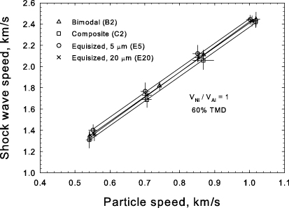
Figure 2. Shock wave speed plotted as a function of particle speed for the equivolumetric 60% dense Ni/Al powders.
Download figure:
Standard image High-resolution imageIn the sections that follow, the particle-level responses of the bimodal powders (mixture class B) and the composite powders (mixture class C) are examined. The particle-level responses of the equal-sized powders (mixture class E) were presented in our previous work [8] and are not repeated here.
5.1. Bimodal powders
Mixture B1 is a Ni-rich spherical powder (5 µm Ni + 20 µm Al). It corresponds to the experimental powder that showed evidence of ultra-fast reaction during wave reflection [3, 4]. The particle-level responses of mixture B1 in the incident (first) shock wave are illustrated in figure 3. Here, the same powder sample has been subjected to stress wave amplitudes of 4.4 and 8.2 GPa. In figure 3(a), mass density fields are plotted to illustrate the deformation of the constituent phases. At 4.4 GPa, the stress wave is strong enough to crush out all mixture porosity. However, the overall deformation is relatively mild, as the pores appear to have collapsed in a relatively orderly fashion. At 8.2 GPa, the Al particles are flattened to a greater extent, appearing more ellipsoidal in shape, with the Ni particles being driven further into them. The Ni particles now form indentations in the Al particles and trap small volumes of Al among them.

Figure 3. Particle-level responses of mixture B1 (Ni-rich, bimodal powder) impacted at 4.4 GPa (left column) and 8.2 GPa (right column): (a) mass density fields, (b) logarithmic temperature fields, and (c) melt fraction fields. The flyer plate impacts the left-hand side of the powder and the incident shock propagates from left-to-right. Regions not occupied by the particles are void of material (dark blue regions ahead of the shock front in part (a)).
Download figure:
Standard image High-resolution imageThe simulated temperature fields (log(T)) are plotted in figure 3(b). Temperature increases are primarily due to inelastic work. There is a small contribution from lattice compression and, currently, no contribution from frictional sliding since the material interfaces are perfectly bonded. At 4.4 GPa, the Al particles are embedded in a Ni matrix that has an average temperature of ∼1000 K. At 8.2 GPa, the average temperature of the Ni matrix is increased to ∼1500 K, with hot spots among the Ni particles reaching ∼3000 K. In both cases, the interiors of the Al particles remain at ∼1000 K, whereas regions near the surfaces of the Al particles are heated to higher temperatures for the stronger shock. The preceding observations are in contrast to our previous findings for mixture class E, wherein the Al particles are uniformly warmer and the Ni particles exhibit cooler interiors [8]. Thus, changes in relative concentration and particle size can lead to differences in the heating of phases.
The melting behaviour of the powder is now examined. Whether or not melting helps to initiate reactions among metallic particles under shock wave loading is an open question. The time scale of ultra-fast reaction is too short to admit a mechanism based on the diffusivity of Ni solutes in liquid Al, at least for micrometre-scale particles [13]. Furthermore, shock compression experiments performed on silicide-forming systems indicate that premature melting of one phase tends to limit the deformation and mixing of the reactants, thus inhibiting the occurrence of ultra-fast reactions [6]. However, the melting of both Al and Ni would give rise to liquid–liquid convective mixing rates that are much faster than diffusion alone. The simulated melt fractions, which characterize the progress of the solid-to-liquid transformation, are plotted in figure 3(c) to illustrate the extent of melting in mixture B1. As mentioned earlier, these calculations take into account the effects of latent heat, loss of strength and viscosity of molten flow. At 4.4 GPa, the simulated melting temperatures of Ni and Al are 1783 K and 1107 K, respectively, and the overall amount of melting within the powder is rather small. At 8.2 GPa, the simulated melting temperatures of Ni and Al are 1831 K and 1264 K, respectively, and there are regions of full melting near the surfaces of the Al particles and a number of tiny Ni melt pools. For this stress level, 5.4 vol% of the Al phase is liquid. Although high strain rates can be found in the molten regions, there is not much additional viscous dissipation in these regions since the deviatoric stresses predicted by the fluid constitutive model are relatively low (<1 MPa).
The particle-level responses of mixture B2 are qualitatively similar to those presented for mixture B1 and are not presented here. The main difference is that the Al particles of mixture B2 appear to be deformed to a slightly lesser extent than those of mixture B1 presumably due to the higher volume fraction of Al in the mixture. Differences in response are better highlighted through quantitative analysis of Ni/Al interface formation, which is carried out in section 5.3.
5.2. Composite powders
Mixture C1 is a Ni-rich powder made up of composite particles (60 µm outer diameter). It corresponds to an experimental powder that showed evidence of flow instability above a threshold impact condition [13]. The particle-level responses of mixture C1 in the incident shock wave are illustrated in figure 4. Here, the same powder sample has been subjected to stress wave amplitudes of 5.2 and 10.1 GPa. At 2.1 GPa (not shown), the pores are not entirely compressed out of the mixture. At 5.2 GPa, the powder is fully crushed but the overall particle deformation is still rather mild, as all Ni/Al interfaces remain intact. At 10.1 GPa, there is a noticeable change in the character of deformation. Jets of Ni are now formed, which impact downstream particles and lead to Ni/Al interfaces that are more disrupted. The Ni shells are fully ruptured in some regions and Ni fragments are found deep within the Al cores. Rupture, in this case, is caused by the thinning of shells due to plastic deformation, as models of damage initiation and growth are not included. An enlarged view of the simulated deformation is given in figure 5(a) to illustrate the jetting. High-speed fluidized jets of Ni, travelling at 2–3 km s−1, are formed as the pores are collapsed. As shown by the lower arrow in figure 5(a), these jets impinge on other particles, causing large deformations and sometimes penetration of neighbouring Ni shells. The upper arrow in figure 5(a) indicates a region where Ni has flowed-in behind the initial jet, producing a bulge in the Al core of the impacted particle. A shock recovery micrograph from the corresponding experimental powder [38] is shown in figure 5(b). In this micrograph, it appears a surface instability has propagated from the Ni/Al interface into the Al core. The intensity of mixing was strong enough for a chemical reaction to occur in this location (the product phase is marked as 'A' in the micrograph). The simulated flow morphology of the inert powder (figure 5(a)) bears some resemblance to the deformation observed in the experiment. The phase morphology observed in the experiment is not precisely reproduced because the Ni and Al phases are modelled as immiscible, inert and free of any cracks, surface roughness or variations in properties that might help to propagate instabilities. At any rate, the simulations suggest that the jetting of Ni during pore collapse is at least partially responsible for surface instabilities observed in the experimental powder.

Figure 4. Particle-level responses of mixture C1 (Ni-rich, composite particle powder) impacted at 5.2 GPa (left column) and 10.1 GPa (right column): (a) mass density fields, (b) logarithmic temperature fields, and (c) melt fraction fields.
Download figure:
Standard image High-resolution image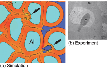
Figure 5. (a) An enlarged view of the simulated deformation of mixture C1 shocked to 10.1 GPa. The arrows indicate regions where jets of fluidized Ni impact the shells of neighbouring particles and cause a bulging of Ni into the Al core; (b) a recovery micrograph from the experimental powder [38] (with permission), which displays evidence of flow instability. Chemical reaction has resulted in a product phase that is marked 'A' in the micrograph. The scale marker in part (b) applies to both images.
Download figure:
Standard image High-resolution imageThe simulated temperature fields for the composite particles (figure 4(b)) display significant heterogeneity because (i) there is preferential deformation of the Ni phase in pore-collapsed regions, and (ii) there is insufficient time for full thermal equilibration of these fairly large particles during a single shock transit. At 10.1 GPa, the Al cores appear to be uniformly heated up to ∼1000 K and the Ni phase displays hot spots of up to 2500 K at points of flow convergence. As shown in figure 4(c), there is very little melting at 5.2 GPa, whereas at 10.1 GPa, pools of molten Ni are found in many of the pore-collapsed regions. These Ni melt pools are, in some places, adjacent to pools of partially melted Al. At 10.1 GPa, only 0.8 vol% of the Al phase is liquid. The elemental powders (B1, B2, E5 and E20) exhibit higher levels of melting in the Al phase because the pore configurations allow for greater deformation of the Al particles. In the composite powders, the Al cores tend to remain encapsulated within the Ni shells, which prevent the flow of Al into the void space.
The Ni coatings in mixture C2 are ∼1 µm thinner than those of mixture C1. The thinner coatings of mixture C2 promote higher levels of simulated shell rupture under shock wave loading. Apart from this difference, the particle-level responses of mixture C2 are qualitatively similar to those of mixture C1 and are not presented here. A quantitative analysis of Ni/Al interface formation in mixture C2 is carried out in section 5.3.
5.3. Ni/Al interface formation
Mass mixing is the rate limiting process in fast reactions. Since chemical reactions originate at the surfaces where Ni and Al come into contact, the dynamics and overall extent of Ni/Al interface formation are of interest. This type of mixing is usually called macromixing or hydrodynamic mixing as opposed to atomic level mixing, which is not addressed here. In our previous work, the surface area of the Ni/Al interface per unit of shocked volume (SV) was calculated for mixtures E5 and E20 and shown to be in reasonable agreement with experimental measurements [8]. These calculations are now extended to the bimodal and composite powders. In figure 6, the specific interfacial area is plotted as a function of shock stress for mixture classes B, C and E. The elemental powders (B1, B2, E20) tend to form larger specific interfacial areas due to the smaller particle size and the simultaneous deformation of constituents in the pore space, whereas the encapsulation of Al within the composite powders (C1 and C2) limits the amount of interfacial area that is formed. Mixture E5 (not shown here, but given previously) forms the largest specific interfacial area, i.e. 200–300 mm−1. The stress sensitivity of interface formation (∂SV/∂σ) has been computed for each powder, with values placed next to corresponding regression lines in figure 6.
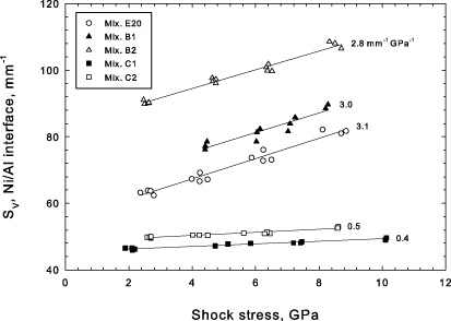
Figure 6. The amount of Ni/Al interface area per unit of shocked volume is plotted versus shock stress for each of the mixtures (excluding E5). Regression lines have been fit to the data; slopes are indicated (in mm−1 GPa−1).
Download figure:
Standard image High-resolution imageThe rate of growth of the Ni/Al interface area is now considered. For a shock wave that advances into a powder at constant speed, D, the rate of interface production may be written as

where A is the transverse cross-sectional area of the powder volume element. Let us denote the normalized growth rate as
 . In figure 7, the normalized interface growth rate is plotted for each of the EV60 powders. In log–log space, the growth rate exhibits a linear dependence on the shock stress. This suggests the existence of a power-law scaling relation, i.e.

The results for the EV60 powders are well-described by a set of lines with nearly identical slopes (n = 0.60 ± 0.03). This indicates that the scaling exponent, n, is constant for a given composition, whereas the scaling coefficient, B, depends on the phase morphology (e.g. particle shape, size, etc). The scaling parameters determined for the EV60 powders and the Ni-rich powders are given in table 3. A scaling relation of the form SV = SV(σ) may be derived from equation (3), i.e.

where the stress dependencies of D and u are conveyed by shock wave speed–particle speed relation and the Hugoniot jump condition.

Figure 7. The normalized rate of Ni/Al interface production for the EV60 powders. The results conform to a scaling law (the solid lines) with an exponent of n = 0.60 and the coefficients given in table 3.
Download figure:
Standard image High-resolution imageTable 3. Scaling law parameters for Ni/Al interface growth rate
 .
.
| B(GPa−n µs−1) | n | |
|---|---|---|
| Equivolumetric powders (60% TMD) | ||
| E5 | 109.1 | 0.60 |
| E20 | 28.7 | — |
| B2 | 41.6 | — |
| C2 | 20.5 | — |
| Ni-rich powders (variable porosity) | ||
| B1 | 25.1 | 0.68 |
| C1 | 26.3 | 0.47 |
5.4. Interface temperature and dislocation density
The previous section focused on the overall size and growth rate of the Ni/Al interface area. We now consider the temperature of the interface and its microstructure, which are relevant to atomic level mixing that occurs across the interface. To quantify the distributed nature of the Ni/Al interfaces, histograms of interface temperature and dislocation density were computed after a single shock transit of the volume element. The histograms are to be interpreted as the area fractions of the Ni/Al interface that fall within the designated bins. Details of the binning procedure were given previously [8].
The histograms of Ni/Al interface temperature are plotted in figure 8(a) for an equal-sized powder (E20), a bimodal powder (B1) and a composite powder (C1). The data points correspond to the bin midpoints, with lines drawn in-between to guide the eye. The number next to each histogram indicates the simulated impact stress. As expected, the mean interface temperature and the width of the distribution increase with shock strength. In mixtures E20 and B1, the upper tails of the distributions extend beyond 1800 K for the highest impact stress, whereas the temperature distributions for mixture C1 are biased towards lower interface temperatures. The details of pore collapse are responsible for this difference. In the elemental powders (E20 and B1), the Ni and Al phases are drawn into the pore space by simultaneous plastic deformation. This raises the temperature of Ni/Al interfaces that are created in pore-collapsed regions. In the composite powder (C1), the pores are filled primarily by the deformation of the Ni shells and Ni/Ni contacts form in the pore-collapsed regions instead of new Ni/Al contacts. Therefore, material in close proximity to the Ni/Al interface is less deformed and resides at lower temperature.
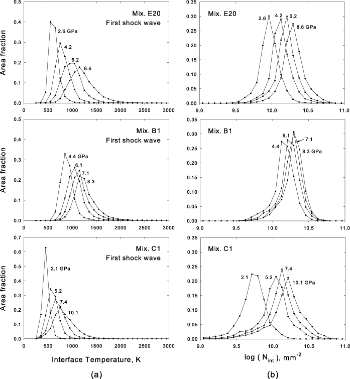
Figure 8. Histograms of (a) Ni/Al interface temperature and (b) interface dislocation density for mixtures that contain equal-sized particles (mixture E20), large Al particles (mixture B1) and composite particles (mixture C1). The number next to each histogram indicates the simulated impact stress (in GPa).
Download figure:
Standard image High-resolution imageThe role of dislocation density in mass mixing is an interesting point to consider. On one hand, mass diffusion is accelerated by the presence of dislocations because pipe diffusion tends to occur along the cores. Furthermore, highly dislocated volumes may be prone to fragmentation, which would accelerate the mixing through exposure of fresh surfaces. On the other hand, elevated dislocation densities serve to strengthen the particles, offering greater resistance to continued plastic flow. Given that dislocation density is an internal state variable in the constitutive models for the solid metallic phases, it seems relevant to quantify dislocation density in the vicinity of the Ni/Al interface. Histograms of interface dislocation density (number of dislocations piercing the interface per unit area) are plotted in figure 8(b) for each of the aforementioned powders. The measure of interface dislocation density was taken as Nint = NNi + NAl, i.e. the sum of the constituent dislocation densities in a computational zone that contains part of the interface. The powders exhibit incremental shifts in interface dislocation density as the impact stress is increased, with the upper tails of the distributions all approaching 1011 mm−2, which is roughly the upper limit of dislocation density in a crystalline material [39]. The histograms of the composite powder (C1) exhibit the widest spread in dislocation density, which indicates these interfaces experience the largest range of deformation conditions. Although there are some slight differences in distribution shape, it would appear that the interfacial dislocation density generated by shock wave loading is not highly sensitive to initial powder configuration, at least for these particle geometries.
The enhanced mass diffusivity around the dislocated interfaces can be estimated using the method described by Shewmon [40]. Equating the diffusivity along a dislocation core to the diffusivity in a grain boundary leads to the following expression for the enhanced diffusivity:

where nc is the number of atoms attributed to the core per unit length of dislocation, n'' is the number atoms per unit area per unit length of dislocation, N⊥ is the dislocation density and D0 and Qgb are the grain boundary diffusivity parameters. Following Horie and Sawaoka [13], Qgb is taken as one-half the activation energy for diffusion in the bulk (which is about 140 kJ mol−1 for intermetallic-forming Ni/Al mixtures), D0 is taken as 10−5 m2 s−1 (a typical value for bulk diffusion in metal–metal couples) and nc/n'' = 5 × 10⁻¹⁹ m−2. For an impact stress of ∼10 GPa, the histograms in figure 8 indicate the mean interface temperatures in mixtures E20 and B1 are about 1200 K, whereas the mean dislocation densities in the vicinity of the Ni/Al interface are about 2 × 1010 mm−2. Therefore, the enhanced diffusivities of mixtures E20 and B1 are estimated to be D* ∼ 10−10 m2 s−1. The characteristic length of mass diffusion for a simple diffusion couple is
 , where D is the diffusivity and t is the elapsed time. Considering the enhanced diffusivity and a shock-loading time scale of 100 ns, the diffusion length is ∼25 nm, which is orders of magnitude smaller than the deformed particle size. Therefore, diffusion enhancements due to elevated temperature and dislocation density do not provide mixing rates fast enough to explain the shock ignition of these micrometre-scale particle systems.
5.5. Velocity fluctuations in reflected waves
The plate impact experiments that were performed on a bimodal Ni/Al powder [3, 4] indicated that the effects of ultra-fast chemical reactions were present in reflected wave signals (see section 2). Therefore, we have simulated wave reflection in our powders to investigate the particle-level responses that may be responsible for shock ignition. The longitudinal velocity fields of mixtures B1, E20 and C1 are plotted in figure 9 to illustrate responses during wave reflection. Please notice the different length scale marker for each volume element and that waves reflected from the backer plate propagate from right to left. The stress jump upon full reflection, Δσ, is indicated (each powder was impacted with an initial flyer velocity of 1.2 km s−1; however, each simulation offers a distinct impedance matching problem). The particle boundaries have been removed from mixtures E20 and C1 to provide unobstructed views of the fields. There are two phenomena of specific interest in figure 9. The first is the appearance of two wave fronts in each of the powders. There is now a quasi-elastic precursor wave that detaches from the main reflected wave. The precursor wave is present during reflection because the first wave crushes out all of the porosity, yielding a fully dense compact composed of shock-hardened grains. The second feature of interest is the non-planarity of the main reflected wave. Undulations are formed in the main reflected shock front because the consolidated powder is a heterogeneous medium that displays spatial variations in density and wave speed. The higher wave speed of Al causes the front to advance more quickly when a patch of Al is encountered, thus producing non-planar fronts. The particle boundaries have been rendered in mixture B1 (the top pane of figure 9) to illustrate this phenomenon. The non-planar fronts gives rise to velocity differentials across the Ni/Al interfaces. Spatial variations in velocity are also present in small pockets behind the reflected front. However, the magnitudes of these velocity differentials tend to be somewhat smaller than those introduced by the front curvature.

Figure 9. Longitudinal velocity fields in the reflected waves are plotted for mixtures B1, E20 and C1. The stress jump upon reflection (Δσ) is indicated for each powder. Regions that are green in colour correspond to the quasi-elastic precursor waves that run ahead of the main reflected waves (regions that are blue in colour). The curvature of the main reflected wave fronts is due to material heterogeneity.
Download figure:
Standard image High-resolution imageThe velocity differentials (or fluctuations) that are generated during wave reflection were quantified for a subset of the powders (B1, C1 and E20). This was done by creating a set of transverse sectioning planes that spanned the width of the reflected front and tracked its motion. The longitudinal velocity profiles on these sectioning planes were inspected for velocity differentials across Ni/Al interfaces. These differentials were reckoned over the length scale of a particle diameter. Ideally, the velocity differential across an interface would be projected into components normal to and tangential to the interface. However, we sought to avoid the burdensome post-processing task of resolving all of the interface normals relative to the shock direction and, instead, have sampled only the longitudinal velocity field to quantify the differential across an interface. In this regard, we limited the sampling to cases for which the approximation is reasonable, i.e. interface normals that are roughly orthogonal to the shock direction. The aforementioned sampling procedure was carried out using multiple time snapshots taken from multiple renderings of each powder. The calculated distributions of particle velocity fluctuation are plotted versus the stress jump upon reflection in figure 10(a). Distinct trends emerge as the stress jump is increased, with the elemental powders (mixtures E20 and B1) displaying larger velocity fluctuations than the composite powder (C1). It is also noted that the dispersion of the velocity distribution increases with the magnitude of the stress jump. The mean values of the distributions are plotted in figure 10(b). The equal-sized powder (mixture E20) displays the largest mean velocity differential for stress jumps up to ∼15 GPa; however, the highest overall mean velocity differentials are achieved in mixture B1, albeit at higher stress jumps. The mean particle velocity fluctuations that are calculated for mixture B1 are in agreement with estimates derived from a continuum mixture theory [41] and the DE method [29].

Figure 10. (a) A sampling of longitudinal velocity differentials (or fluctuations) across the Ni/Al interfaces in the reflected shock fronts; the mean values of each distribution are plotted in part (b). The stress jumps were generated by flyer initial velocities in the range of 0.6–1.2 km s−1.
Download figure:
Standard image High-resolution imageVelocity differentials across Ni/Al interfaces are also present in the incident shock wave, prior to wave reflection. For example, when mixture E20 is shocked up to 8.6 GPa from the ambient state, longitudinal velocity differentials of up to 2.0 km s−1 are generated when jets of one phase pass over another in regions where the pores are collapsed. Likewise, velocity differentials of up to 0.5 km s−1 are calculated when mixture B1 is shocked up to 7.1 GPa from the ambient state. There is clearly a potential to drive large velocity differentials in the front of the incident shock wave, although these velocity differentials are generated in environments of low confinement, i.e. in regions among the pores. The velocity differentials that are computed further behind the shock front, under the confinement pressure of the first wave, are significantly lower. For example, the mean velocity differentials that are generated under confinement in the incident wave are 0.091 km s−1 for mixture E20 (shocked up to 8.6 GPa) and 0.046 km s−1 for mixture B1 (shocked up to 7.1 GPa). These velocity differentials are smaller than those generated in the subsequent reflection waves, which produce stress jumps of 15.6 GPa and 16.2 GPa in mixtures E20 and B1, respectively (see figure 10(b)).
In the next section, we consider fine-scale mixing processes that are not resolved in the FE simulations but may be excited by the aforementioned velocity differentials. Since the experimental records for the powders under consideration indicate quite definitively that reactions do not occur during the passage of the incident shock wave, our analysis will focus on fluctuations in the reflected wave.
5.6. Reduction of mixing length scale by particle fragmentation
The velocity differentials discussed in the previous section are associated with shearing processes that involve Ni/Al interfaces. It seems reasonable to hypothesize that such shearing events would involve localized grain refinement [42], especially in light of nearly saturated dislocation densities near the interfaces. This notion is similar to the idea of Batsanov [43], which involves shock-induced particle fracturing and interpenetration in an environment of high strain gradients and high defect concentrations. To explore this idea, we consider a model of shock-induced crystal refinement that was proposed by Horie and Yano [42]. The model is a shear-based analogue of the Grady model [44], which addresses the dynamic fragmentation of rapidly expanding solids. The basic idea is that the local kinetic energy (i.e. the total kinetic energy minus the centre-of-mass kinetic energy) is transformed to the energy of new interfaces between comminuted material fragments. This transformation is described by the following energy balance:

The left-hand side of equation (6) is the amount of local kinetic energy that is transformed from a uniformly sheared block and the right-hand side is the energy density of the new interfaces, assuming cubic fragments of size λ. Here, ρ is the mass density, Δu is the velocity differential generated across the block by the shearing, ε is a process efficiency parameter, γ is the interface energy density and f is the volume fraction of the system that is fragmented. From equation (6), the fragment size may be written as

This mixing length scale allows for the consideration of grain refinement under shock wave loading, which is not resolved in the particle-level FE calculations.
The expected fragment sizes for Ni and Al are now calculated independently as functions of Δu using equation (7). Following Yano and Horie [29], it is assumed that the local kinetic energy is fully transformed (ε = 1) and that this energy is localized in 10% of the system (f = 0.1). The interface energy density is taken as one-third of the equilibrium free surface energy [13], which is denoted as γs and given in table 2. The preceding assumptions represent, in some sense, an optimistic scenario for generating tiny fragments and therefore a lower bound on λ. The fragment sizes for Ni and Al are plotted as functions of Δu in figure 11.

Figure 11. The reduced mixing length scale (i.e. fragment size) is plotted for Ni and Al as a function of particle velocity fluctuation. The critical velocity fluctuation, above which shock initiation is expected, corresponds to that which renders the fragment sizes smaller than the characteristic dimension of mass diffusion over 100 ns (the approximate shock rise time in these powders).
Download figure:
Standard image High-resolution image
If the particle velocity fluctuations across the Ni/Al interfaces are sufficiently strong to reduce λ to the characteristic length of mass diffusion under shock wave loading, then high-yield chemical reactions are enabled by diffusive mass transport among the refined grains. As shown in figure 11, the fragment sizes of both Ni and Al are rendered smaller than the diffusion length scale, xdiff ∼ 25 nm (see section 5.4), for velocity fluctuations above a critical value (Δucritical ∼ 0.120 km s−1). This threshold is plotted in figure 10(b). Based on the mean velocity fluctuations that were computed in the reflected waves using the FE model, mixture B1 is expected to undergo shock ignition at the two highest loading conditions (i.e. stress jumps of 16.2 GPa and 17.5 GPa, which correspond to stainless steel flyer velocities of 1.1 km s−1 and 1.2 km s−1, respectively). This powder does, in fact, exhibit signs of shock ignition in the reflected wave for experiments performed at these loading conditions [4]. Stress jumps of greater than ∼14 GPa were sufficient to initiate reactions in the experimental powder, whereas the simulated ignition threshold is ∼16 GPa. The difference between the experimental threshold and the predicted threshold stems from differences in the reflection stresses that were measured (σ = 21.0 GPa) and calculated (σ = 23.3 GPa) for an impact velocity of 1.1 km s−1. Thus, the model is in agreement with the experimentally observed threshold for shock ignition in mixture B1. Accordingly, the hypothesis that velocity fluctuations across reactant interfaces are responsible for the ultra-fast mixing and reaction of grains refined down to the nanoscale appears to be promising but remains to be fully confirmed. Wave reflection is not a necessary requirement for shock ignition of the Ni/Al system, as experiments performed on mixtures containing Ni flakes (∼300 nm in thickness) have demonstrated ultra-fast reactions in incident shock waves, prior to any wave reflection, for stress jumps of sufficient magnitude [7]. However, the current work suggests that grain fragmentation induced during wave reflection is one possible way to initiate ultra-fast reactions in micrometre-scale Ni/Al powders.
6. Summary and conclusions
A numerical model has been used to study the deformation and mixing of several micrometre-scale Ni/Al powder mixtures under shock wave loading. The model, which is framed at the particle length scale, provides insights into the effects of initial powder configuration on the coupled thermal–mechanical responses of the aggregates under shock wave loading. In this regard, the responses of six distinct Ni/Al powders have been investigated, i.e. powders composed of equal-sized spherical Ni + Al particles (mixture class E), powders that display a bimodal distribution of particle size (mixture class B) and powders composed of Ni-coated Al particles (mixture class C). The novel aspects of this work include: (i) the Ni/Al powders that were simulated (i.e. the bimodal and composite particle powders), (ii) the use of a rate-dependent, dislocation-based model of particle flow stress in the shock-loading calculations, (iii) the monitoring of reactant interfaces during wave propagation and (iv) the investigation of powder responses during wave reflection.
In heterogeneous material systems, the macroscopic rates of mass mixing and reaction depend on the amount of reactant interfacial area that is present and on conditions induced at those interfaces. Accordingly, attention has been focused on the Ni/Al interfaces that are formed under shock wave loading. The calculations allowed for a rank ordering of powders based on the dynamics and overall extent of reactant interfacial area formation. The calculations also allowed for the identification of a scaling relation that describes the rate of Ni/Al interface production as a function of shock stress (equation (3)). Interestingly, the scaling exponent, n, was found to depend only on mixture composition and not on initial phase morphology. Furthermore, this scaling relation implies another scaling relation for overall interfacial area (equation (4)). These scaling relations may find utility in macroscopic models that do not resolve the details of particle deformation but seek to include reactant interfacial area as an internal variable. Finally, histograms of Ni/Al interface temperature and dislocation density were calculated to quantify conditions that may accelerate mixing processes across the interfaces under shock wave loading.
The simulations of shock wave reflection revealed two phenomena of interest: (i) the appearance of quasi-elastic precursor waves that run ahead of the main reflected wave fronts and (ii) velocity differentials (or fluctuations) across Ni/Al interfaces in the reflected shock fronts. The velocity differentials stem from the non-uniform properties of the densified powders. The distributions of velocity fluctuation were computed in a set of powders over a range of stress jump upon reflection. A model of grain fragmentation was then used to estimate a reduced mixing length scale based on the average level of velocity fluctuation across the Ni/Al interfaces. The reduced mixing length scale corresponds to the size of fragments that are produced when local kinetic energy is converted to the energy of new reactant interfaces. Above a critical threshold, the velocity fluctuations are sufficient to refine the grains to sizes smaller than the diffusion length scale under shock wave loading. When this threshold is exceeded, ultra-fast reactions can be explained on the basis of enhanced diffusion among the shock-refined, nanometric grains. The shock ignition threshold that is predicted for mixture B1 (Δσ ∼ 16 GPa) is in reasonable agreement with the experimentally observed threshold (Δσ ∼ 14 GPa), which suggests shear-driven grain fragmentation is a potential explanation for ultra-fast reactions in the experimental powder.
In future work, the current model could be rendered more realistic by including provisions for damage initiation and growth, and frictional sliding among the particles. Modelling the particles as individual crystals instead of isotropic bodies might also lead to interesting localization effects such as shear banding (although such an effect would be more pronounced for crystals of lower symmetry). Further analysis might also be carried out to rank order various powders according to combined metrics; for example, metrics that account for which powders display the strongest velocity fluctuations and, simultaneously, the highest rates of reactant interface production. The former would account for the propensity of local initiation along reactant interfaces, whereas the latter would convey information on the tendency for large-scale ignition (reaction propagation) based on the speed at which new interfacial area is produced. Finally, it may be useful to investigate the behaviour of Ni/Al bilayers using atomistic simulation, as highly resolved simulations of bilayer shearing over some range of interface roughness and confinement pressure may provide insights into the mechanisms of refinement and fine-scale mixing under shock wave loading.
Acknowledgments
This research was carried out under the support of the NDSEG fellowship programme and the AFRL Munitions Directorate (Y Horie, technical monitor). DLM is grateful for the support of the Carter N Paden, Jr Distinguished Chair in Metals Processing and NSF CMMI grant 0758265 on Multiresolution, Coarse-Grained Modelling of 3D Dislocation Nucleation and Migration. This work was performed, in part, under the auspices of the US Department of Energy by Lawrence Livermore National Laboratory under contract DE-AC52-07NA27344 (LLNL-JRNL-635678).