

Abstract
This paper presents a new jetting dispenser which is applicable to high-frequency microelectronic packaging. In order to achieve high frequency glue jetting and improve the stability of jetting dispensers, we redesign a novel displacement amplifying mechanism, and a new on–off valve jetting dispenser driven by piezoelectric actuators is developed. Firstly, the core part of this jetting dispenser—the displacement amplifying mechanism with a corner-filleted flexure hinge—is proposed and a comparison with the previous structure is carried out; then the characteristic dimensional parameters of the amplifying mechanism are determined by theoretical calculation and finite element analysis. Secondly, a prototype of the dispenser with the displacement amplifying mechanism is fabricated based on the determined parameters. We use a laser displacement sensor to test the displacement of the needle, and a maximum amplifying displacement output of 367 µm is obtained under an applied 200 V to the piezoelectric actuator, which is consistent with the simulation result and meets the requirement of high displacement output. Thirdly, we build an integrated testing system. Mixed glycerol/ethanol is chosen as the experimental dispensing glue, and the experiment and analysis of a droplet diameter are conducted. A higher jetting frequency of 400 Hz and a smaller droplet diameter of 525 µm are achieved with the glycerol/ethanol mixture, and the characteristics of consistency and temperature influencing the droplet diameter are verified by experiments.
Export citation and abstract BibTeX RIS
1. Introduction
Fluid dispensing [1–5] is a key technology of the microelectronic packaging industry [6]. Point, line, surface and other forms of motion trail can be formed in a specific manner by utilizing this accurate fluid allocation technology. Therefore, it can transfer an ideal fluid size (such as solder, conductive glue, epoxy, UV glue, etc) to the proper position of the workpiece (chip, electronic components, etc), achieving a mechanical or electrical connection between the components. With the development of intensive applications, such as die attach, underfill, die coating techniques, especially micro-electromechanical systems [7], a significant challenge for high-speed, high-stability fluid dispensing technology has arisen.
According to the different principles of fluid dispensing, it can be classified into contact dispensing [8, 9] and non-contact jet dispensing [10–12]. Due to low efficiency and the fact that the needle is vulnerable to damage, contact dispensing technology is severely restricted, so nowadays, non-contact jet dispensing has become a dominating fluid dispensing technology because of its high efficiency and because the needle is invulnerable to damage. The driving methods of jet dispensing technology can also be classified into a piezoelectric actuator [13], a pneumatic actuator [14], and an electromagnetic actuator [15]. In recent years, jet dispensing technology with a piezoelectric on–off valve [16–18] has had very important applications in microelectronic packaging, which has prompted many research institutions to focus on jetting technology, especially on on–off valve jet dispensing technology. Lu et al [19] proposed a type of jetting dispenser driven by a piezostack, which used the bond-graph technique, and it has been demonstrated that the agreement between the simulation and experiment is favorable. Jeon et al [20] presented a jetting dispenser system which is adaptable to light emitting diode packaging and flip chip packaging, etc. It has been shown from an experimental investigation that the maximum displacements of the needle and response time were 0.33 mm and 0.3125 ms, respectively. Du et al [21] proposed a jet dispensing technique which could achieve a maximum frequency up to 200 Hz with a dot consistency of ±10%. Zhou et al [22] designed a novel jetting dispenser with giant magnetostriction and a magnifier. The jetting frequency can increase to 250 Hz, and the velocity and displacement of the jetting needle reaches 320 mm · s−1 and 0.11 mm respectively. However, these jetting dispensers can hardly reach a steady jetting frequency over 300 Hz, which cannot meet the requirements of the modern microelectronic packaging industry. Moreover, the short lifetime of these needles, o-rings and piezoelectric actuators at a high frequency is also a challenge.
Previously, we developed an on–off valve jetting dispenser [16] with a nozzle diameter of 250 µm. The maximum jetting frequency at which the jetting dispenser can steadily work is 65 Hz, and the consistency of the droplet diameter is within ±2%. Although it cannot achieve the required performance, the feasibility of this jet dispensing system is verified sufficiently. On the basis of this work, in response to the requirements of high efficiency in the jetting technology of microelectronic packaging, another innovative piezostack driven on–off valve jetting dispenser is designed and developed in this paper to achieve high frequency. Firstly, a displacement amplifying mechanism with a corner-filleted flexure hinge (hereafter referred to as a flexible hinge) is proposed, and the type of piezoelectric actuator is determined. Theoretical calculation and finite element software ANSYS are both used to acquire the optimum dimensional parameters of the mechanism. Then, this amplifying mechanism is fabricated and tested by experiments which prove the validity of the simulation and calculation. Finally, experiments of the displacement amplifying mechanism are carried out by driving piezoelectric actuators; a driving scheme is obtained and a steady viscous fluid jetting is ultimately achieved.
2. Design of jetting dispenser
2.1. Configuration of the jetting dispenser
Based on the flexible hinge, we propose a new displacement amplifying mechanism. As shown in figure 1, a rotating arm with a flexible hinge is attached to the entity structure and the piezoelectric actuator. Two piezoelectric actuators are fastened symmetrically with a rotating arm by limited blocks, respectively. Meanwhile, the position of each limited block is adjusted by a tension bolt which also adjusts the preload force on the piezoelectric actuator. If the upper piezoelectric actuator is energized to elongate, the rotating arm will rotate counterclockwise with a small angle, which can drive its associated displacement amplifying block to rotate together, outputting an upward amplifying displacement in the front; similarly, if the lower piezoelectric actuator is energized to elongate, an amplifying displacement will be output downward. Thus, the amplifying mechanism can produce a reciprocating displacement if the upper and lower piezoelectric actuators are applied with the square-wave voltage of different phases, respectively.
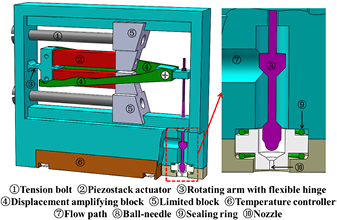
Figure 1. Schematic of the proposed jetting dispenser.
Download figure:
Standard image High-resolution image2.2. Comparison of previous and current structures on piezoelectric actuators
In our previous jetting dispenser (see figure 2(a)), it was found that the piezoelectric actuator is vulnerable to damage, indicating that excess stress occurs in the piezoelectric actuator. Therefore, a stress simulation comparison of previous and current structures on piezoelectric actuators is carried out. As shown in figure 2(b), it is apparent that the new mechanism has lower equivalent and shear stress, which reduces by 69% and 68%, respectively. Compared to the previous displacement amplifying mechanism, this structure is based on a lever amplifying principle, which can simply and reliably acquire a larger magnification. The piezoelectric actuator is arranged transversely in its direction of elongation, so it reduces the overall size of the dispenser effectively. Owing to two adjustable limited blocks, the amplifying mechanism can also use various types of piezoelectric actuators with different lengths. Compared to other asymmetric flexible hinge mechanisms, this mechanism will barely lead to elongation of the tension bolt which has a high stiffness, so the flexible hinge is under a slight compression, and lateral excursion does not occur in the displacement output. In addition, since the flexible hinge is always under squeezing, the overall structure can be kept in an approximately steady state, thus it possesses a relatively larger resonant frequency.
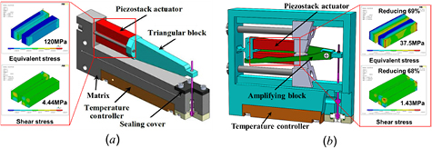
Figure 2. Comparison of previous and current jetting dispenser (a) previous; (b) current.
Download figure:
Standard image High-resolution image2.3. Theory and simulations of the displacement amplifier
2.3.1. Theoretical calculations.
Figure 3(a) shows the dimension parameters of the amplifying mechanism, wherein the design parameters of the flexible hinge include fillet radius R, thickness t, and straight beam length h. Unfortunately, these important parameters affect the displacement output and the resonant frequency of the amplifying mechanism, so they need to be emphatically discussed. Meanwhile, with the purpose of reducing the displacement output loss, the high-stiffness limited block should be designed; in other words, the stiffness of the limited block needs to be much greater than that of the flexible hinge, which is squeezed by two piezoelectric actuators. The force analysis is shown in figure 3(b), where a is half the length of the rotating arm. Moreover, elongation loss depends on the stiffness of the external mechanical structure, and higher external structural stiffness will increase the elongation loss. Therefore, the ceramic elongation is related to the bending stiffness of the flexible hinge.
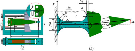
Figure 3. (a) Dimension parameters of the amplifying mechanism; (b) the schematic of force analysis for a corner-filleted flexure hinge.
Download figure:
Standard image High-resolution imageThe flexible hinge is composed of an arc segment and a straight beam segment. For the arc segment, the rectangular coordinate should be changed to a polar coordinate; namely, the formulas are:
where α is the polar angle. For the straight beam segment, it is still in a rectangular coordinate, and the formula is:

When a force F is applied, the flexible hinge will be under a torque Mz, and the formula of the bending stiffness k [21] is as follows:
where
where b is the width of the flexible hinge, and E is the Young's modulus of the flexible hinge. When one of the piezostacks is energized to drive the flexible hinge, a deflection angle θ will be generated because of the elongation, as shown in figure 3(b), where ▵lp is the actual elongation of the piezoelectric actuator.
According to the principle of lever amplification, the final displacement output of the amplifying mechanism is:
Finally, the formulas derived above can be simultaneously carried out to obtain the theoretical result of the final displacement output.
2.3.2. Simulations.
Significant parameters (such as the bolt diameter D, the length L of the displacement amplifying block, preload force P, etc) also need to be determined. Before finite element analysis, it is necessary to pre-determine the material characteristics of different components, and each parameter is preset in table 1. Furthermore, the flexible hinge usually works under frequently alternating force, so characteristics of spring steel should be chosen for simulation. Considering the size, response time and cost of the piezoelectric actuators, a lead zirconate titanate piezoelectric actuator (PSt-HD 200) which can elongate 45 µm without preload force under a voltage of 200 V is selected, and its stiffness is 35 N µm−1. Based on the original amplifying mechanism above, the model is simplified and imported to finite element software ANSYS; the meshed model is shown in figure 4. With different structural parameters, simulations of the amplifying mechanism are conducted with piezoelectric actuators which can elongate by 45 µm. Therefore, the maximum displacement output, which is represented by the front point F, is obtained. Meanwhile, in order to ensure that the amplifying mechanism will not be damaged and can work over a long period, the stress should be kept at a lower level. Generally, since the flexible hinge has a smaller cross-section and is subject to greater pressure from the piezoelectric actuator, the maximum stress occurs only on the flexible hinge in the whole structure.
Table 1. Dimension and material characteristics of different components.
| Component | Amplifying block | Tension bolt | Piezostack | Corner-filleted flexure hinge |
|---|---|---|---|---|
| Value | L = 40 mm | D = 4 mm | 7 mm × 7 mm × 32.5 mm | R = 1 mm h = 1 mm t = 1 mm |
| a = 9 mm b = 8 mm | ||||
| Material | Steel | Steel | Ceramic | Spring steel |
| Density | 7850 kg · m−3 | 7850 kg · m−3 | 7700 kg · m−3 | 7810 kg · m−3 |
| Young's modulus | 2 × 10¹¹ (Pa) | 2 × 10¹¹ (Pa) | 3.4 × 10¹¹ (Pa) | 2.06 × 10¹¹ (Pa) |
| Poisson's ratio | 0.3 | 0.3 | 0.22 | 0.29 |
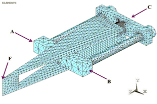
Figure 4. The simplified model in ANSYS.
Download figure:
Standard image High-resolution imageThe following factors are simulated by a controlling variable method, and impacts of various parameters on the displacement output and maximum stress are analyzed. The results are shown below in figure 5. With the growing length of the displacement amplification block, the displacement output increases linearly, as shown in figure 5(a), while the maximum stress of the amplifying mechanism remains almost the same, indicating that dimension changes have little impact on the maximum stress of the flexible hinge. To control the overall size of the jetting dispenser and a certain closing pressure, a reasonable length L of the displacement amplifying block should be selected. For the most stress-concentrated flexible hinge, the displacement output increases along with the hinge radius R in the simulation, while the maximum stress significantly decreases. But if the radius R increases to more than 3 mm, the curve tends to be smooth, as shown in figure 5(b), which means the maximum stress is slightly influenced with a larger radius R. Similarly, the larger straight beam segment h decreases the stress and increases the displacement output in the simulation, as shown in figure 5(c); t is the thickness of the flexible hinge which is also an important factor that determines the stiffness and performance of the amplifying mechanism. In figure 5(d), the displacement output and maximum stress both correspondingly decrease as the hinge thickness t increases. Therefore, it is necessary to choose a larger thickness t for a higher stiffness, which can avoid fatigue damage in the flexible hinge after a long-term working period. The impact of the bolt diameter D on the displacement output of the amplifying mechanism is shown in figure 5(e), which demonstrates that a larger bolt diameter D gives cause for a larger displacement output. But if the bolt diameter increases to more than 6 mm, the displacement output tends to change little, indicating that the stiffness of the bolt diameter is much larger than that of the piezoelectric actuator and no longer affects the displacement output. Thus, it can be determined according to the parameters of the flexible hinge determined above. In addition, the preload force P produced by the bolt increases from 0 N–2000 N, and the simulation results are shown in figure 5(f). The displacement output reduces slightly as the preload force P changes, while the maximum stress increases linearly. The results indicate that preload force has little influence on the displacement output. Meanwhile, the piezoelectric actuators are symmetrically arranged on both sides of the flexible hinge, so it can be speculated that the increasing stress on the flexible hinge is mainly caused by the preload force. Therefore, a smaller preload force should be considered with fixed piezoelectric actuators.
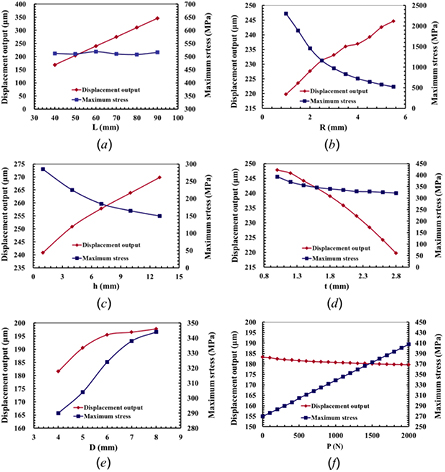
Figure 5. Relationships between the displacement output, maximum stress and various parameters: (a) length L of the amplifying block; (b) radius R; (c) straight beam h; (d) hinge thickness t; (e) bolt diameter D; (f) preload force P.
Download figure:
Standard image High-resolution imageAccording to the simulations of various parts of the amplifying mechanism and requirements of the actual design, the optimum dimensions of each part can be determined, as shown in table 2. With these determined parameters, a rebuilt model of the amplifying mechanism is imported to ANSYS. The displacement output of the amplifying mechanism is 350 µm according to the simulation result, and the maximum stress of the flexible hinge is 180 MPa, which is lower than the allowable fatigue stress of spring steel and can ensure a long-term working time with less fatigue damage. Meanwhile, the determined optimum parameters are put into the theoretical formulas above and the calculated displacement output is obtained to be 363 µm. Compared with the simulation result, a relative error of 3.8% is acquired, which is caused by preload force settings in the simulation, so the error is within the acceptable range.
Table 2. Determined dimensions of the structure.
| Component | Amplifying block | Bolt | Corner-filleted flexure hinge | ||||
|---|---|---|---|---|---|---|---|
| Dimension | L = 86 mm | D = 7 mm | R = 2 mm | h = 3 mm | t = 1 mm | a = 9 mm | b = 8 mm |
Since the displacement amplifying mechanism in the dispenser is actually running under dynamic conditions, in order to avoid damages caused by high-frequency resonance, the resonant frequency of the displacement amplifying mechanism also needs to be simulated. The six-order modal vibrations are shown in figure 6. In the modal simulation, the first, second and third orders of modal vibrations actually work perpendicular to the vibrating direction of the amplifying mechanism, and therefore they do not have a negative impact on the actual jetting. Only the fourth vibrating mode is working at the vibrating direction, and its resonant frequency reaches 1216 Hz. Compared to the existing dispensers with a maximum operating frequency of 500 Hz, this resonant frequency can still ensure safe working conditions, and can effectively work at a high frequency.
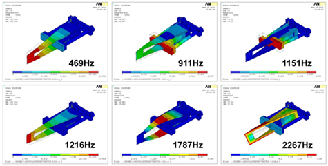
Figure 6. Modal analysis of the amplifying mechanism.
Download figure:
Standard image High-resolution image3. Experiments and discussions of the jetting dispenser
Figure 7(a) shows the testing schematic of the displacement output. Its displacement is measured by a high-speed, high-precision laser displacement sensor produced by Keyence. The laser displacement sensor is connected to a power source and a computer, and the laser is aligned with a needle tip. The experiment in which a piezoelectric actuator is connected to a DC source, with another connected to a square-wave voltage, is carried out, and then the displacement data measured by the laser displacement sensor is recorded on the computer. By changing the signal amplitude performances of the displacement, the amplifying mechanism can be obtained. By keeping the frequency at 10 Hz, the duty cycle at 50% of the square-wave signal and the preload force at 100 N, the relationship between the displacement output and the amplitude of the square-wave voltage is shown in figure 7(b). The corresponding displacement output rises linearly when the voltage amplitude gradually increases to 200 V, so the final displacement can be adjusted by changing the voltage during the dispensing process. The curve does not pass through the origin, indicating that the displacement output under a small square-wave amplitude is assimilated by the preload force. When a square-wave voltage of 200 V is applied, a displacement output of 367 µm is acquired, and, compared with the finite element simulation result of 350 µm, an error of 4.6% is calculated which verifies the accuracy of the simulation.
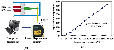
Figure 7. (a) Testing schematic; (b) relationship between the displacement output and amplitude of the input square-wave.
Download figure:
Standard image High-resolution imageAccording to the required function, the prototype of the jetting dispenser is fabricated for experimental testing, and an integrated dispensing testing system includes an assembled jetting dispenser, a piezo-drive power supply, a temperature controlling module, oscilloscope and so on, as shown in figure 8. In the experiment, a glycerol/ethanol mixture with a viscosity of 180 cps is used, and the conditions are as follows: gas pressure of 6 bar, nozzle diameter of 200 µm, square-wave driving voltage of 180 V, duty cycle of 50%. Then a curve of diameter variation is obtained by changing the frequency of the square-wave signal, as shown in figure 9. Since a shorter dispensing cycle is caused by a higher square-wave frequency, the open time of the needle reduces correspondingly, and it can jet a smaller volume of glue in one cycle if the duty cycle is constant, therefore a smaller droplet diameter can be produced. In the experiment, the square-wave frequency is increased from 5 Hz–100 Hz, and the droplet diameter reduces accordingly from 5 mm–1.5 mm, while the square-wave frequency increases from 100 Hz–400 Hz, and the droplet diameter reduces from 1.5 mm to about 0.5 mm. According to the results of the displacement output, it can be seen that the displacement output has a significant impact on the glue volume because the average displacement output per cycle is apparently reduced at a lower frequency which produces a smaller glue volume, while at a high frequency, the average displacement output per cycle is reduced inconspicuously despite the short response time of the piezostack, and the thus obtained droplet diameter reduces more slowly. So far, a smaller droplet diameter of 525 µm has been steadily obtained, and at a high frequency of 400 Hz, the dispenser is still able to jet smaller droplets.
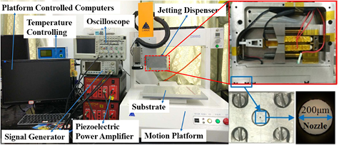
Figure 8. Experimental apparatus of the jetting dispenser.
Download figure:
Standard image High-resolution image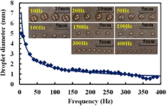
Figure 9. Relationship between droplet diameter and square-wave frequency (voltage amplitude: 180 V; duty cycle: 50%; nozzle diameter: 200 µm; viscosity: 180 cps; gas pressure: 6 bar).
Download figure:
Standard image High-resolution imageIn order to obtain consistency in the droplet diameter, the results at the frequency of 350 Hz are chosen according to the experiment shown in figure 9. A 6 × 18 dot array with an average diameter of 0.755 mm is obtained, as figure 10 shows, in which the variation of the droplet diameter is within ±2%. In addition, with a temperature controller, a change in the droplet diameter along with temperature can be conducted. As for the theoretical analysis, it is known that glue viscosity decreases with the rising temperature, so it will be easier for the glue to flow out from the nozzle as the temperature increases, making the glue droplet much larger. As shown in figures 11(a) and (b), pure glycerol with a viscosity of over 800 cps is used; the droplet diameter changes with the temperature, and the higher temperature leads to a larger droplet. The curve becomes flat when the temperature gradually increases due to the smaller change of the glue viscosity at a higher temperature. Based on all the results above, it is proved that this amplifying mechanism with a corner-filleted flexure hinge is suitable for the jetting dispenser in current microelectronic packaging.
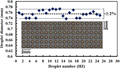
Figure 10. Variation of the droplet diameters for the jetting dispenser (voltage amplitude: 180 V; duty cycle: 50%; frequency: 350 Hz; nozzle diameter: 100 µm; viscosity: 180 cps; gas pressure: 6 bar).
Download figure:
Standard image High-resolution image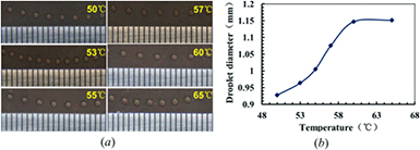
Figure 11. (a) Testing pictures at different temperatures; (b) relationship between droplet diameter and temperature (voltage amplitude: 180 V; frequency: 100 Hz; duty cycle: 50%; nozzle diameter: 100 µm; viscosity: ⩾800 cps; gas pressure: 8 bar).
Download figure:
Standard image High-resolution image
4. Conclusion
In this paper, a displacement amplifying mechanism based on a corner-filleted flexure hinge was designed, fabricated and tested with piezostack driving. The maximum displacement output was measured as 367 µm. Based on the above, a dispensing system was established for the testing. Then a glycerol/ethanol mixture was chosen as the dispensing glue, and the relationship between the droplet diameter and the square-wave frequency was obtained in the experiments. Under designated conditions, a higher frequency of 400 Hz and an average droplet diameter of 525 µm were achieved with steady dispensing, which proves that the amplifying mechanism based on a corner-filleted flexure hinge is capable of meeting the requirements of high-frequency, and also a small droplet diameter. At the same time, it was found that a decrease in equivalent stress and shear stress does prolong the service life of the structure compared with the previous one. Based on our present experimental results, the current dispenser has not damaged any one of the piezostack actuators to date, although it has dispensed more than 50 million droplets. But the previous dispenser damaged four piezostack actuators under the same conditions and about the same number of cycles. In addition, the proposed jetting dispenser has successfully achieved continuous and accurate jetting by controlling the input voltage, but this work is not the end. So, the following main work focuses on the control circuit design which also has the function of points counting, to test the lifespan and the amount of points of every single mission. Through technical comparison, the maintenance cycle we hope to achieve is about 200–300 million points, and the consistency of the glue point in the high frequency application is below 2%. After the experimental verification of this mechanism, there are great demands of miniaturization and optimization according to recent developments, such as improving manufacturing technologies, smaller-droplet jetting technologies, and new emerging colloids. Therefore, our subsequent work will focus on these new demands in order to produce a more advanced jetting dispenser.
Acknowledgments
This work was supported by the Main Project in Science and Technology Plan of Fujian Province (No. 2015H6022). This work was also partly supported by the National Natural Science Foundation of China (No. 61674125).