

Abstract
This paper presents a design approach to determine the bending stiffness of the flexible hinge in electromagnetically driven artificial flapping-wing insects for improved lift force. The prototype insects are fabricated by laser cutting technique and have a wingspan of 3.6 cm and a total mass of 84 mg. To induce effective wing rotational movements for improved aerodynamic performances, the geometric parameters of the flexible hinge in the wing rotation mechanism are optimized based on lift force simulations and bending stiffness tests on the enlarged flexible hinges. With an applied AC current of 420 mA (AC voltage of 0.5 V), the prototype #4 with optimized flexible hinge can produce effective wing rotational movements with a maximum rotation angle of 50° and a flapping amplitude of ±50.6° at 65 Hz. Such wing movements can generate a measured average lift force of 384.5 µN to produce a total lift force to weight ratio of 0.47. With this magnitude of lift force, the prototype can slide on a tilted guide rail with an inclined angle of 7°. Such results validate the feasibility of the design approach of the flexible hinge in the artificial insects for improved lift force.
Export citation and abstract BibTeX RIS
1. Introduction
Flapping-wing insects, such as honey bees and dragonflies, possess impressive agility and maneuverability among living flying species [1–3]. Over the past two decades, the pursuit of outstanding artificial insects with aerial capabilities similar to those of natural flapping-wing insects has set off a new wave of research targeting small-size systems with wingspan less than 5 cm [4–18]. During flapping flight, insects rotate their wings at certain moment in flapping sequence to generate sufficient lift force [19–22]. To emulate these wing movements, passive wing rotation design by using flexible hinge is widely adopted in artificial insects considering its simple structure and easiness in fabrication [9, 11, 23–25]. Based on passive wing rotation mechanism, many attempts have been made for the flapping flight of artificial insects and the most notable example is the 'RoboBee' [2, 9, 10, 26] developed at Harvard University. However, in these state-of-art artificial flapping-wing insect demonstrations, the flexible hinge in the passive wing rotation mechanism is highly customized and its design approach has not been fully addressed, which limits its further application in other artificial insect systems.
In passive wing rotation mechanism, the artificial wing passively rotates under the combined action of aerodynamic force and wing inertial. The wing rotation angle (the angle between the wing plane and plumb plane) during the wing strokes is determined by both the aerodynamic force and the bending stiffness of the flexible hinge. On the other hand, the aerodynamic force is directly related to the wing rotation pattern [19, 20, 23, 24, 27–30], which means the bending stiffness of the flexible hinge plays a crucial role in aerodynamic force generation. For flexible hinge, current researches mainly focus on its fabrication methods [9, 23, 31–34] and fatigue characteristics [33], while the design approach of its bending stiffness and the corresponding effects on artificial insects' aerodynamic performance are rarely involved.
In this work, we present a design approach of the flexible hinge in electromagnetically driven artificial flapping-wing insect for desired wing rotational movements and improved lift force. The prototype artificial insects are fabricated by using laser cutting technique and carbon fiber based materials. To optimize the geometric parameters of the flexible hinge in the wing rotation mechanism, lift force simulations and bending stiffness tests on the enlarged flexible hinge are conducted. The wing rotational movement and lift force are tested experimentally. To visually demonstrate the effective lift force, two types of guide rails including a horizontal one and a tilted one are designed and the sliding motions on both guide rails are observed in the prototype experiments.
2. Design
2.1. System configuration
Figure 1(a) presents the overall view of the artificial flapping-wing insect, consisting of an electromagnetic actuator, a set of transmission mechanism, two sets of wing rotation mechanisms, two artificial wings, and an airframe. The actuator outputs vibratory motion of a cantilever-plate to drive the artificial wings via the transmission mechanism for the flapping movements. The vibratory electromagnetic actuator is chosen for actuation considering its low operating voltage and simple structure [1, 16]. The wing rotation mechanism is set at the wing root to induce rotational movement during the wing flapping sequences. The airframe provides the structural support for the whole system. Figure 1(b) shows an optical photo of the prototype with a total wingspan of 3.6 cm.
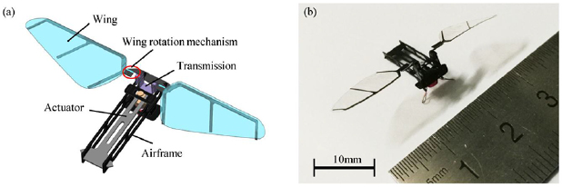
Figure 1. (a) Schematic diagram of the artificial flapping-wing insect. (b) Optical photo of the prototype with a total wingspan of 3.6 cm.
Download figure:
Standard image High-resolution image2.2. Wing rotation mechanism
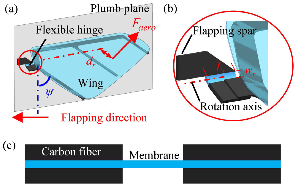
In this investigation, a passive wing rotation mechanism is adopted as shown in figure 2. A flexible hinge is set at the wing root to connect the flapping spar and the artificial wing. When the artificial wing flaps, the aerodynamic and wing inertial force will cause the wing to passively rotate around the rotation axis and a wing rotation angle, ψ, defined as the angle between the plumb plane and the wing plane, is formed. In the passive wing rotation mechanism, the flexible hinge is made of plastic membrane and it can be considered as a thin plate with an overall bending stiffness, D. Based on thin plate bending theory, the wing rotation angle can be approximately given by [35]:

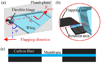
Figure 2. (a) Schematic diagram of the passive wing rotation mechanism by using a flexible hinge at the wing root. (b) Enlarged view of the flexible hinge. (c) Cross section of the flexible hinge.
Download figure:
Standard image High-resolution imageWhere dr is the distance from the acting point of the concentrated aerodynamic force Faero to the rotation axis; wr is the width of the flexible hinge; and Lr is the length of the flexible hinge. The bending stiffness, D, of the flexible hinge is determined by the geometric parameters (thickness t, length Lr, width wr) and the material properties of the plastic membrane (E is elastic modulus and υ is poison ratio). The determination of bending stiffness of the flexible hinge in wing rotation mechanism is further elaborated in section 4.
2.3. Actuator
Figure 3(a) shows the schematic diagram of the electromagnetic actuator, consisting of a permanent magnet, a cantilever plate, and an electromagnet with an iron core. The permanent magnet is glued to the free end of the cantilever plate and the electromagnet is set below the permanent magnet. When an AC current is applied to the electromagnet at the natural frequency of the cantilever system (including cantilever plate and permanent magnet), the cantilever plate will be excited into resonance for vibratory motions.
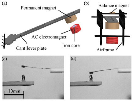
Figure 3. (a) Schematic diagram of the electromagnetic actuator. (b) The actuator is mounted to the airframe and a balance magnet is used to prevent the initial deformation of the cantilever plate. (c) and (d) Optical photos of the electromagnetic actuator during the vibration motions captured by a high speed camera. The cantilever plate is made of carbon fibers and it is 15 mm in length, 1.5 mm in width and 0.1 mm in thickness.
Download figure:
Standard image High-resolution imageIt is noted that an iron core is inserted into the coil for the purpose of providing large periodically-driven force with decreased applied AC current as compared with the commonly used hollow coil [1, 15, 16]. As shown in figure 3(b), to prevent the initial deformation of the cantilever plate, a small balance magnet is put at the other side of permanent magnet to counteract the attraction force between the iron core and the permanent magnet. Figures 3(c) and (d) are the optical photos of the electromagnetic actuator under vibration at 223 Hz captured by a high speed camera. The cantilever plate made of carbon fibers is 15 mm in length, 1.5 mm in width and 0.1 mm in thickness. The peak to peak vibration amplitude can reach 3.6 mm with an applied AC current of 420 mA.
2.4. Transmission mechanism
The flapping movement of the artificial wings is transformed from the actuator to the wings via the transmission mechanism. As shown in figure 4(a), a set of transmission mechanism based on the principle proposed by the 'RoboBee' [26, 32] is adopted in this investigation. The transmission mechanism is glued to the free end of the cantilever plate and then fixed to the airframe and the artificial wings are mounted to the rotating part of the transmission mechanism.
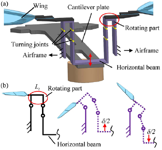
Figure 4. (a) Schematic diagram of the transmission mechanism. (b) Working principle of the transmission mechanism.
Download figure:
Standard image High-resolution imageThe transmission mechanism is designed based on leverage principle. By using the flexible turning joints, the upward and downward vibratory motion of the cantilever plate can be transformed into the reciprocating flapping movement of the artificial wings, as shown in figure 4(b). The peak to peak flapping amplitude 2ϕ of the artificial wings is mainly determined by the peak to peak vibration amplitude δ of the cantilever plate and the rocker length Lt of the transmission mechanism. The approximate relation between ϕ and δ can be given by [26]:
3. Fabrication
In this investigation, carbon fiber based composite materials and high precision laser cutting technique are utilized to fabricate the artificial flapping-wing insect prototypes. Figure 5 illustrates the detailed fabrication procedures. The wingspan of the prototype is 3.6 cm and the overall mass is 84 mg. Table 1 illustrates the mass of each component of the artificial insect prototype.
Table 1. Mass of each component of the prototype.
| Component | Mass (mg) |
|---|---|
| Actuator | 62.2 |
| Transmission mechanism | 5.6 |
| Wing rotation mechanism | 2.0 |
| Wings | 1.4 |
| Airframe | 12.8 |
| Total | 84.0 |
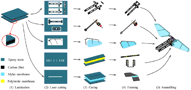
Figure 5. Fabrication procedure of the artificial flapping-wing insect.
Download figure:
Standard image High-resolution image3.1. Airframe
Carbon fiber lamination material is selected for airframe considering its high specific strength. Firstly, two layers of unidirectional carbon fiber prepreg sheets (Toray T300-3K, Japan) are glued to each other by the epoxy resin. The directions of the carbon fibers are vertical to each other to enhance the strength of the structure. After the lamination process, different parts of the airframe are cut into designed shapes by using a high precision laser cutting machine (Optical fiber laser marking system, Planck PLS-20B, China) and then cured under 80 °C for 2 h. After the curing process, these parts are assembled by mounting flanges and grooves and super glue (Pattex precision, Germany) is used at the mounting groove.
3.2. Actuator
The fabrication procedure of the actuator mainly focuses on its assembly process. The cantilever plate in the actuator is cut into designed shape on unidirectional carbon fiber prepreg layers by laser and then cured. The cantilever is 13 mm in length, 1.5 mm in width and 0.15 mm in thickness. After the curing process, a permanent magnet (NdFeB, 25 mg) is fixed to the free end of the cantilever plate by using super glue (Pattex precision, Germany). The electromagnet is fixed to a carbon fiber plate and mounted to the airframe along with the cantilever plate. Afterwards, the balance magnet (NdFeB, 3 mg) is glued to the airframe, as shown in figure 3(b).
3.3. Wings
To ensure the structural strength of the artificial wings, the wing venation is cut from the lamination of multiple carbon fiber prepreg layers and the angle between the carbon fibers is determined by the wing venation pattern [36]. After the wing venation is processed by laser cutting, the wing membrane, which is cut from a 2.5 µm-thick Mylar membrane (Chemplex, USA) by laser, is glued to the wing venation by epoxy resin. These two parts are cured under 80 °C for 2 h to allow the epoxy resin to solidify and form a strong bond. During the curing process, an additional weight is put on the wing plane to prevent warpage. The length of the artificial wing is 12 mm and its maximum chord width is 6.25 mm.
3.4. Transmission mechanism
The difficulty in fabricating the transmission mechanism is the flexible turning joints. In this investigation, the lamination of unidirectional carbon fiber prepreg layers is firstly cut into the designed shape by laser and a 7.5 µm-thick polyimide membrane (DuPont USA) is then glued to the carbon fiber prepreg layers by epoxy resin. Afterwards, a second premachined lamination of unidirectional carbon fiber prepreg layers is put on the polyimide membrane. After the curing process, the transmission mechanism is cut from the lamination materials by laser and folded into the designed shape by using super glue (Pattex precision, Germany). The rocker length, Lt, of the transmission mechanism is 0.5 mm.
3.5. Wing rotation mechanism
The wing rotation mechanism is also fabricated by using carbon fiber—membrane—carbon fiber lamination material. In this investigation, three types of plastic membrane (2.5 µm-thick, and 6 µm-thick Mylar membrane from Chemplex USA; 7.5 µm-thick Polyimide membrane from DuPont USA) are used in the fabrication process for the flexible hinge optimization.
4. Flexible hinge optimization
The bending stiffness of the flexible hinge in passive wing rotation mechanism is related to the aerodynamic force and wing rotation angle according to equation (1). In this investigation, the aerodynamic force and the optimal maximum wing rotation angle are determined based on quasi-steady state aerodynamic model. The time varying wing flapping angle and rotation angle are firstly obtained as the input parameters of the aerodynamic model.
4.1. Lift force simulation
The flapping amplitude and frequency are the two key parameters for the flapping movement. Figure 6 shows the step by step photos of the wing flapping movement captured by a high speed camera (Optronis CL600, Germany) from the top view. The peak to peak flapping amplitude is obtained by analyzing the high speed images frame by frame. It is noted that the prototype #1 in this test is utilized to preliminary determine the flapping amplitude and frequency, while the wing rotational movement is not optimized. The thickness of the flexible hinge in the wing rotation mechanism is 7.5 µm (Polyimide membrane, DuPont USA) and the length and width are 2 mm and 0.5 mm, respectively. The flapping frequency of the prototype is 62.2 Hz and the sampling frequency of the high speed camera is set to 2000 frames per second. With an applied AC current of 420 mA, the prototype can achieve a peak to peak flapping amplitude of 98.5°.
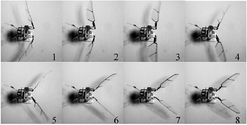
Figure 6. Step by step photos of the wing flapping movement captured by a high speed camera.
Download figure:
Standard image High-resolution imageIn this prototype, the rocker length, Lt, of the transmission mechanism is 0.5 mm. Based on equation (3), the peak to peak vibration amplitude, δ, of the cantilever plate is calculated as 0.86 mm. To further increase the flapping amplitude, an effective way is to increase the vibration amplitude δ.
In a flapping cycle, the wing rotation angle generally varies sinusoidally [9]. Once the maximum wing rotation angle and flapping frequency are given, the time varying wing rotation angle can be depicted. Under the assumption that both the flapping angle and rotation angle vary sinusoidally, the aerodynamic lift force can be estimated by the quasi-steady state aerodynamic model [20, 29, 37]. This model is also used in predicting aerodynamic lift force generated by micromechanical flying insect (MFI) developed in UC Berkeley [29]. Considering the measured wing inertial force and added mass force by surrounding fluid are negligible as compared with the translational and rotational force, the added mass force and inertial force components are neglected in this model [20].
It is noted that the applicable Reynolds number of the quasi-steady state aerodynamic model ranges from 100 to 1000 [20]. The estimated Reynolds number of prototype #1 is close to 600, which means the aerodynamic model is appropriate for the lift simulation in this investigation. The aerodynamic force acting at the center of pressure of the wing can be given as [29, 37]:
In this model, ρ is the density of the air; CN, CT and Crot are dimensionless force coefficients. For a given wing morphology, A is the wing area; L is the wing length; Ucp is the velocity at the center of pressure; r2 and c2 are normalized wing length and rotational chord width at the center of pressure; and cm is the maximum wing chord width. The subscripts 'tr' and 'rot' represent the aerodynamic force components due to flapping and rotational movements, respectively. The subscripts 'N' and 'R' indicate whether the direction is normal or tangential to the wing plane.
The translational force coefficient CN and CT are functions of the angle of attack α (the coangle of the wing rotation angle ψ) [37].

The rotational force coefficient Crot is approximately independent of the angle of attack α [37].

Where x0 is the dimensionless distance of the longitudinal rotation axis from the leading edge. In most flying insects, x0 is about 0.25.
The normalized wing length r2 and rotational chord width c2 at the center of pressure can be given as [37]:
In most flying insects, the approximate range of r2 is 0.6–0.7 and the approximate range of c2 is 0.5–0.7 [37]. Table 2 shows the symbols and their physical meanings in the lift force simulation.
Table 2. Symbols in lift force simulation.
| Symbol | Physical meaning | Value |
|---|---|---|
| ρ | Air density | 1.29 kg m−3 |
| CN, CT, Crot | Dimensionless force coefficients | — |
| A | Wing area | 55.6 mm2 |
| L | Wing length | 12 mm |
| cm | Maximum wing chord width | 6.25 mm |
| ψ | Wing rotation angle | — |
| ϕ | Wing flapping angle | — |
| c2 | Normalized wing chord width | 0.71 |
| r2 | Normalized wing length | 0.67 |
| Ucp | Velocity at center of pressure | — |
The optimal maximum rotation angle is calculated using the lift force simulations. Based on the test results of the flapping movement (ϕ = 49.2°, f = 62.2 Hz), the flapping amplitude is set to 50° and the flapping frequency is set to 60 Hz in these simulations. Figure 7(a) shows the simulated lift force generated by a single wing when the maximum wing rotation angle is 45°. Figure 7(b) shows the maximum instantaneous lift force and average lift force under different maximum wing rotation angles. The simulation results indicate the optimal maximum wing rotation angle during the flapping movement should be close to 45°. When the maximum wing rotation angle is 45°, the maximum instantaneous lift force is calculated as 524 µN.
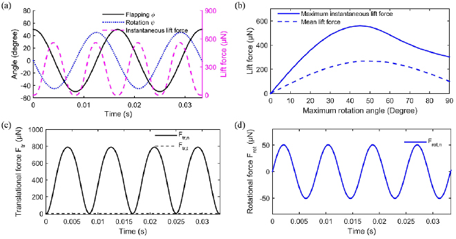
Figure 7. (a) The simulated instantaneous lift force when the maximum wing rotation angle is set to 45°. (b) The simulated maximum instantaneous lift force and average lift force under different maximum wing rotation angles. (c) and (d) The calculated translational and rotational force components when the maximum wing rotation angle is 45°.
Download figure:
Standard image High-resolution imageFigures 7(c) and (d) show the calculated translational and rotational force components when the maximum wing rotation angle is 45°. The translational force is the major component of the aerodynamic force. Since the angle of attack is below 45° during the whole cycle (CT = 0), the tangential translational force component is kept at zero. The simulation results also indicate the overall contribution of rotational force component during a cycle is zero.
4.2. Bending stiffness test
After obtaining the optimal maximum wing rotation angle and corresponding maximum instantaneous lift force, the next step is to determine the geometric parameters of the flexible hinge. Based on equations (1) and (2), the geometric parameters of the flexible hinge in the wing rotation mechanism can be given as:
To exclude the possible effect of the curing process on the material parameters of the membrane, the geometric parameters of the flexible hinge can not be directly calculated by using equation (10). In this investigation, the geometric parameters of the flexible hinge are obtained based on the calculated lift force and the test results of bending stiffness of the enlarged flexible hinges. As shown in figure 8(a), the enlarged flexible hinge is fixed to a cantilever beam, which is mounted to a 3D micrometer stage. When the cantilever beam moves downward, the flexible hinge will contact the vertical pin on the electronic balance. The bending deformation of the flexible hinge can be obtained from the micrometer stage and the applied force can be recorded by the electronic balance [36]. The rotation angle can be calculated using the bending deformation and the distance d0 from the vertical pin to the rotation axis. The length Lr0 of the flexible hinge is 5 mm and its thickness is 6 µm (Mylar membrane, Chemplex USA). The width wr0 of the flexible hinge is set to four different values: 0.1, 0.3, 0.6, 0.9 mm.
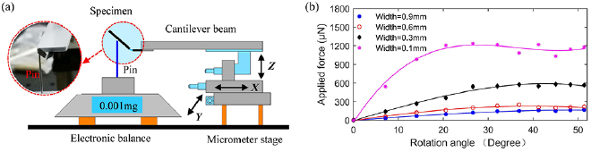
Figure 8. (a) The schematic diagram of the test platform to measure the bending stiffness of the enlarged flexible hinge. (b) The relation between the applied force and the rotation angle with respect to different enlarged flexible hinges with different widths wr0.
Download figure:
Standard image High-resolution imageFigure 8(b) shows the relation between the applied force and rotation angle. When the rotation angle exceeds 20°, the increase rate of the applied force reduces smoothly, which also indicate the bending stiffness of the flexible hinge can not be directly calculated by equations (2) and (10). For the enlarged flexible hinge with width of 0.3 mm, the applied force is close to 580 µN when the rotation angle reaches 45°. The geometric parameters of the enlarged flexible hinges can be derived as:
By comparing equations (10) and (11), the geometric parameters of the flexible hinge in the wing rotation mechanism can be given as:
Where dr = 0.65 mm, d0 = 2 mm, wr0 = 0.3 mm, Lr0 = 5 mm, Flift = 524 µN, Fapplied = 580 µN, ψmax = 45°. Based on equation (12), the optimal length to width ratio Lr/wr is 6.93. For a flexible hinge with width wr = wr0 = 0.3 mm, the optimal length Lr is 2.07 mm. The symbols and their physical meanings in flexible hinge optimization are listed in table 3.
Table 3. Symbols in flexible hinge optimization.
| Symbol | Physical meaning | Value |
|---|---|---|
| Lr | Length of optimized flexible hinge | 2.07 mm |
| wr | Width of optimized flexible hinge | 0.3 mm |
| t | Membrane thickness | 6 µm |
| dr | Distance from center of pressure to rotation axis | 0.65 mm |
| Flift | Maximum instantaneous lift force | 524 µN |
| E | Elastic modulus of membrane | — |
| υ | Poisson's ratio of membrane | — |
| ψmax | Maximum wing rotation angle | 45° |
| Lr0 | Length of enlarged flexible hinge | 5 mm |
| wr0 | Width of enlarged flexible hinge | 0.1–0.9 mm |
| d0 | Distance from vertical pin to rotation axis | 2 mm |
| Fapplied | Applied force to the enlarged flexible hinge | — |
4.3. Wing rotational movements
To validate the optimized parameters of the flexible hinge, three prototypes with different flexible hinges in the wing rotation mechanism are fabricated and their wing rotational movements are recorded by the high speed camera. For prototype #2, the thickness of the flexible hinge is 2.5 µm (Mylar membrane). The length and width are 10 mm and 0.5 mm, respectively. For prototype #3, the thickness of the flexible hinge is 7.5 µm (Polyimide membrane). The length and width are 2 mm and 0.15 mm, respectively. For prototype #4, the thickness of the flexible hinge is 6 µm (Mylar membrane). The length and width are 2.07 mm and 0.3 mm as suggested by the optimization results.
Figure 9 shows the step by step photos of the wing rotational movements with respect to the three prototypes. The wing rotational movement is recorded from side view and the wing rotation angle is obtained by analyzing the high speed images frame by frame. In figure 9(a) for prototype #2, the wing rotational movement has an obvious over rotation pattern due to the low bending stiffness of the flexible hinge. The maximum rotation angle nearly reaches 90° and the rotation angle is negative when the wing starts to change its flapping direction. This pattern is similar to the delayed wing rotation mode described in [19], which is considered unbeneficial for the lift force generation. As shown in figure 9(b) for prototype #3, there is almost no wing rotation pattern due to the overlarge bending stiffness of the flexible hinge. Such wing movement will generate little lift force according to equation (4). For prototype #4, the artificial wings demonstrate an effective wing rotation pattern with a maximum wing rotation angle of 50°, as shown in figure 9(c). When the wing starts to change flapping direction, the wing rotation angle is close to zero and such pattern fits well with the wing movements in the lift force simulation, as shown in figure 7(a). For these three prototypes, the peak to peak flapping amplitude is 100.4°, 80.2° and 101.2° respectively.
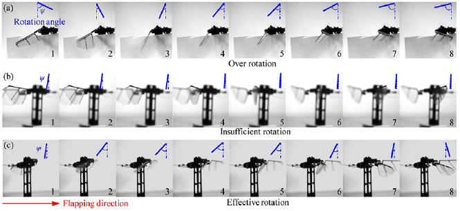
Figure 9. Step by step photos of the wing rotational movements captured by the high speed camera. (a) Over rotational motions by prototype #2. (b) Insufficient rotational motions by prototype #3. (c) Effective rotational motions by prototype #4. Please see the supplementary videos for more information (stacks.iop.org/JMM/29/015011/mmedia).
Download figure:
Standard image High-resolution imageFigure 10 shows the time-resolved wing flapping and rotational angles, and their first (velocity) and second order time derivatives (acceleration) of these three prototypes. For prototype #2, the angle of attack is negative (figure 10(a)) during half a stroke due to the low bending stiffness of the flexible hinge. Based on the aerodynamic model, the negative angle of attack will results in negative CN and normal translational force. For prototype #3, the minimum angle of attack α is 85° (the maximum wing rotation angle is 5°, as shown in figure 10(d)), which will lead to large positive normal translational force, while the vertical lift force component is still small since Fvertical = Ftr,ncosα. According to above analysis, the lift force is directly related to the wing rotation pattern.
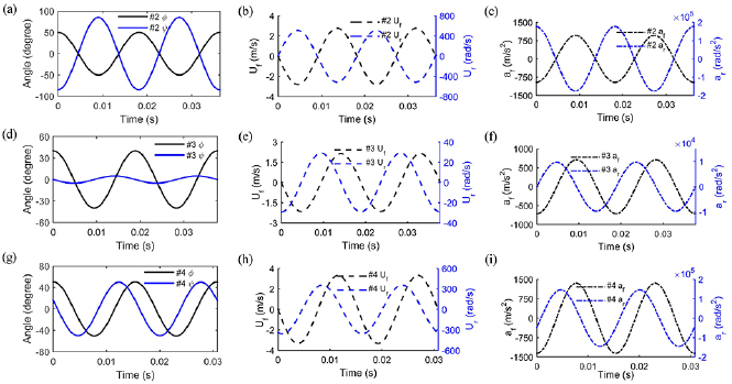
Figure 10. Time-resolved plots of wing flapping and rotational angles, and their first (velocity) and second order time derivatives (acceleration) for these three prototypes.
Download figure:
Standard image High-resolution imageIt is noted that the geometric parameters of the flexible hinge is optimized based on lift force simulations, in which the flapping amplitude and frequency of prototype #1 is used as input parameters. By using optimized parameters, the measured maximum wing rotation angle of prototype #4 is 50°. As shown in figure 7(b), when the flapping amplitude and frequency are kept constant and the maximum wing rotation angle ranges from 45° to 50°, the average lift forces remain almost unchanged. However, once the flexible hinge is further optimized for the maximum wing rotation angle of 45°, the flapping amplitude and frequency, and the resulting lift force as well, will also slightly change accordingly. Therefore, the optimization of the flexible hinge for improved lift force is an iterative process.
5. Aerodynamic lift force
To measure the aerodynamic lift force generated by these prototypes, a testing system capable of obtaining instantaneous lift force is designed [13, 24]. As shown in figure 11(a), the prototype system is fixed to one end of a lever and placed on the probe of a force sensor (Aurora scientific 403A, Canada). At the beginning of the tests, the probe of the force sensor is under compression due to extra weight of the prototype. The aerodynamic lift force generated by the prototype is obtained by recording the pressure changes of the force sensor.
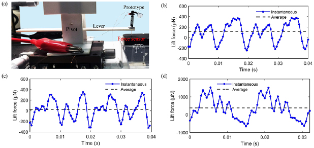
Figure 11. (a) The testing system designed to measure the instantaneous lift force generated by the prototypes. (b) Instantaneous and average lift force for prototype #2 with the over rotational motions. (c) Instantaneous and average lift force for prototype #3 with insufficient rotational motions. (d) Instantaneous and average lift force for prototype #4 with effective rotational motions.
Download figure:
Standard image High-resolution imageFigures 11(b)–(d) show the instantaneous and average lift force generated by the three prototypes in two cycles under an applied AC current of 420 mA. The flapping frequency of these prototypes ranges from 53 Hz to 65 Hz due to the assembly variations. The artificial wings go through the highest flapping velocity twice in each cycle such that two major peaks are observed in the time varying lift force measurement. It is observed that the wing quickly rotates at the beginning and at the end of each lateral flapping cycle and two local peaks are also observed in half a cycle. The measured lift force and frequency are 118.5 µN at 55 Hz, 29.2 µN at 53 Hz, and 384.5 µN at 65 Hz, for prototypes #2, #3, and #4, respectively. The best lift force from prototype #4 can provide a lift force to weight ratio of 0.47.
Based on the wing kinematics, the inertial power of a single wing can be given as:

Where af is the flapping acceleration; Uf is flapping velocity; ar is the rotation acceleration; Ur is the rotation velocity. By using the measured relation between the applied force and rotation angle of the flexible hinge, the elastic power of the flexible hinge can also be estimated.

Figure 12 shows the time resolved plots of wing inertial power and elastic power for these three prototypes (single wing). Since prototype #2 and #4 can achieve large flapping and rotation amplitude, the wing inertial power is 0.98 mW and 1.23 mW respectively, which is larger than the wing inertial power (0.34 mW) of prototype #3. The elastic power of the flexible hinge is 0.022 mW, 0.007 mW and 0.075 mW for prototype #2, #3, and #4, respectively. The parameters of prototype #2, #3, and #4 are listed in table 4.
Table 4. The parameters of prototype #2, #3, and #4.
| Prototype #2 | Prototype #3 | Prototype #4 | |
|---|---|---|---|
| Length of flexible hinge, Lr | 10 mm | 2 mm | 2.07 mm |
| Width of flexible hinge, wr | 0.5 mm | 0.15 mm | 0.3 mm |
| Thickness of flexible hinge, t | 2.5 µm | 7.5 µm | 6 µm |
| Material of flexible hinge | Mylar | Polyimide | Mylar |
| Peak to peak flapping amplitude | 100.4° | 80.2° | 101.2° |
| Maximum wing rotation angle | 85° | 5° | 50° |
| Flapping frequency, f | 55 Hz | 53 Hz | 65 Hz |
| Average lift force | 118.5 µN | 29.2 µN | 384.5 µN |
| Wing inertial power | 1.96 mW | 0.68 mW | 2.46 mW |
| Elastic power of flexible hinge | 0.044 mW | 0.014 mW | 0.15 mW |
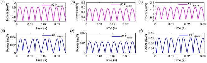
Figure 12. Time-resolved plots of wing inertial power and elastic power of the flexible hinge for these three prototypes in two cycles.
Download figure:
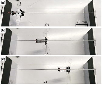
Standard image High-resolution imageTo demonstrate the lift force visually, a horizontal guide rail and a guide rail with a tilted angle made of regular needles are designed as shown in figure 13. When an AC current is applied, prototype #4 can slide on the horizontal guide rail from left to the right with a velocity of 2 cm s−1. When the prototype is put on the tilted guide rail with an inclined angle of 7°, the prototype can still climb and slide with a lower velocity at 0.5 cm s−1.
Figure 13. The optical photos of the prototype #4 sliding on a horizontal guide rail. Please see the supplementary videos for more information.
Download figure:
Standard image High-resolution image
It is noted that the main purpose of this investigation is to provide a design approach of the flexible hinge in artificial insects for enhanced aerodynamic performance. To further enhance the lift force for the final takeoff of the artificial insect, the future optimization should focus on improving the output power of the actuator for larger flapping amplitude. Based on the lift force simulations, when the peak to peak flapping amplitude is increased to 140°, the artificial flapping-wing insect can achieve a total lift force to weight ratio of over 1. According to equation (3), the vibration amplitude δ of the cantilever plate should increase to 1.2 mm when the flapping amplitude is 140°. Apart from the applied current, the vibration amplitude δ is mainly determined by the initial position of the permanent magnet between the electromagnet and the balance magnet (see figure 3(b)). In these prototypes, the free distance between the balance magnet and the electromagnet is 2 mm, which is too large to fully exploit the electromagnetism between the electromagnet and the permanent magnet. By decreasing the free distance between the balance magnet and the electromagnet, it is possible to further increase the flapping amplitude for a large value of lift force to weight ratio. Other optimization approaches include replacing the iron core with more suitable materials such as Ni–Zn ferrite for larger electromagnetic force and increasing flapping frequency by adjusting the stiffness of the vibratory cantilever system.
6. Conclusion
This paper presents a design approach of the flexible hinge in electromagnetically driven artificial flapping-wing insect for desired wing rotational movements and improved lift force. By using laser cutting technique and carbon fiber based lamination materials, the mass of the artificial flapping-wing insect can be reduced to 84 mg and its wingspan can be reduced to 3.6 cm. The test results reveal that the wing rotation movements and aerodynamic lift force is directly related to the bending stiffness of the flexible hinge in the wing rotation mechanism. With an applied AC current of 420 mA, the prototype #4 with optimized flexible hinge can achieve a maximum wing rotation angle of 50° and a flapping amplitude of ±50.6° at 65 Hz. Such wing movements generate an average lift force of 384.5 µN and leads to a total lift force to weight ratio of 0.47. With this magnitude of lift force, the prototype can slide on a tilted guide rail with an inclined angle of 7°. Future works will aim at increasing the flapping amplitude and frequency for larger lift force to achieve the successful takeoff of the artificial flapping-wing insects.
Acknowledgments
This work is supported by China Scholarship Council (CSC, 201506020261), National Natural Science Foundation of China (Grant No. 11602010 and No. 51505018), and the 111 Project (Grant No. B08009).